


Rockshaft and 3-Point Hitch
PY80265,05GO858 –19–29DEC06–1/1
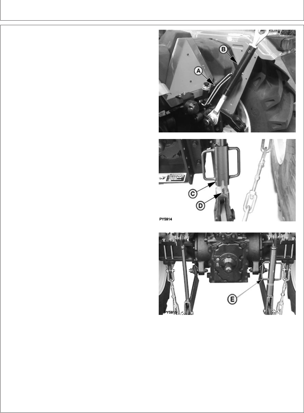
Leveling the Hitch
PY4968 –UN–23APR05PY5914 –UN–12JUL06
For 5103, 5103S, 5203, 5104 and 5204 Tractor
PY5915 –UN–12JUL06
For 5103E Tractor
A—Locking Clip
B—Center Link Body
C—Locking Handle
D—Slot
1. Lower implement to take weight off hitch.
IMPORTANT: DO NOT attempt to overextend center
link beyond limits of locking clip or lift
links past the stops. Link body threads
could be damaged.
NOTE: Maximum adjustment range of the center link can
only be obtained if the ends are positioned equally
within the body when attached to an implement.
2. Adjust center link to level implement front-to-rear.
Unlatch locking clip (A). Rotate center link body
clockwise to lengthen center link or counterclockwise to
shorten it. Be sure to latch the locking clip.
3. Adjust right-hand link to level implement side-to-side.
Lift locking handle (C) and turn 1/4 turn to engage slot
(D) onto roll-pin in the center portion of the lift link.
Turn crank handle (C) clockwise to raise draft link.
Turn crank handle (C) counterclockwise to lower draft
link.
After adjustment, lift handle (C) and turn to engage slot
(D) onto the lower body to prevent change of
adjustment during operation.
4. The left-hand lift link is also adjustable in length to
accommodate different tyre sizes.
To change the left-hand lift link length, remove the
upper lift link pin and rotate the upper end assembly
clockwise to shorten or counterclockwise to lengthen,
and then reinstall the upper pin and locking pin.
Adjust left and right lift links to accommodate various
tyre sizes. Set the lift links to have fully-lowered draft
link balls approximately seven inches off the ground for
greatest range of usable hitch motion.
55-10
022607
PN=63