


Rockshaft and 3-Point Hitch
PY80265,05GO859 –19–10SEP05–1/1
Adjusting Lateral Float
PY5381 –UN–10DEC05
PY5380 –UN–10DEC05
A—Pin in Vertical Position
B—Pin in Horizontal Position
To allow the draft link to raise slightly as implement
follows ground contour, place head of float pin and the
rectangular washer on the inside end of the pin in a
vertical position (A).
To hold implement rigid, place head of float pin and the
rectangular washer in the horizontal position (B).
Use lift link pins in the float position for hitch-mounted
implements such as a cultivator or mower, which have
ground gauging skids or wheels which may cause the
implement to twist relative to the tractor.
Use the rigid position for implements such as plows and
ground engaging implements that should not twist relative
to the tractor.
PY80265,05GO860 –19–10SEP05–1/1
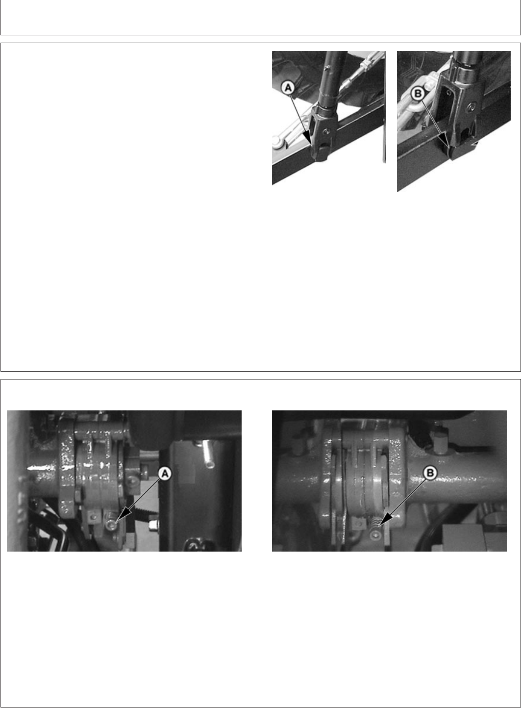
Adjusting Rockshaft Control Lever Friction
PY4406 –UN–10DEC05
PY4385 –UN–10DEC05
A—Adjustment Set Screws B—Adjustment Set Screws
Back Side Of Control Lever Front Side Of Control
Lever
If the rockshaft position control lever or rockshaft draft
control lever do not stay in set position, increase lever
friction by tightening the set screws (A) for the
appropriate lever until the proper friction is obtained.
55-11
022607
PN=64