


Rockshaft and 3-Point Hitch
PY80265,05GO856 –19–10SEP05–1/1
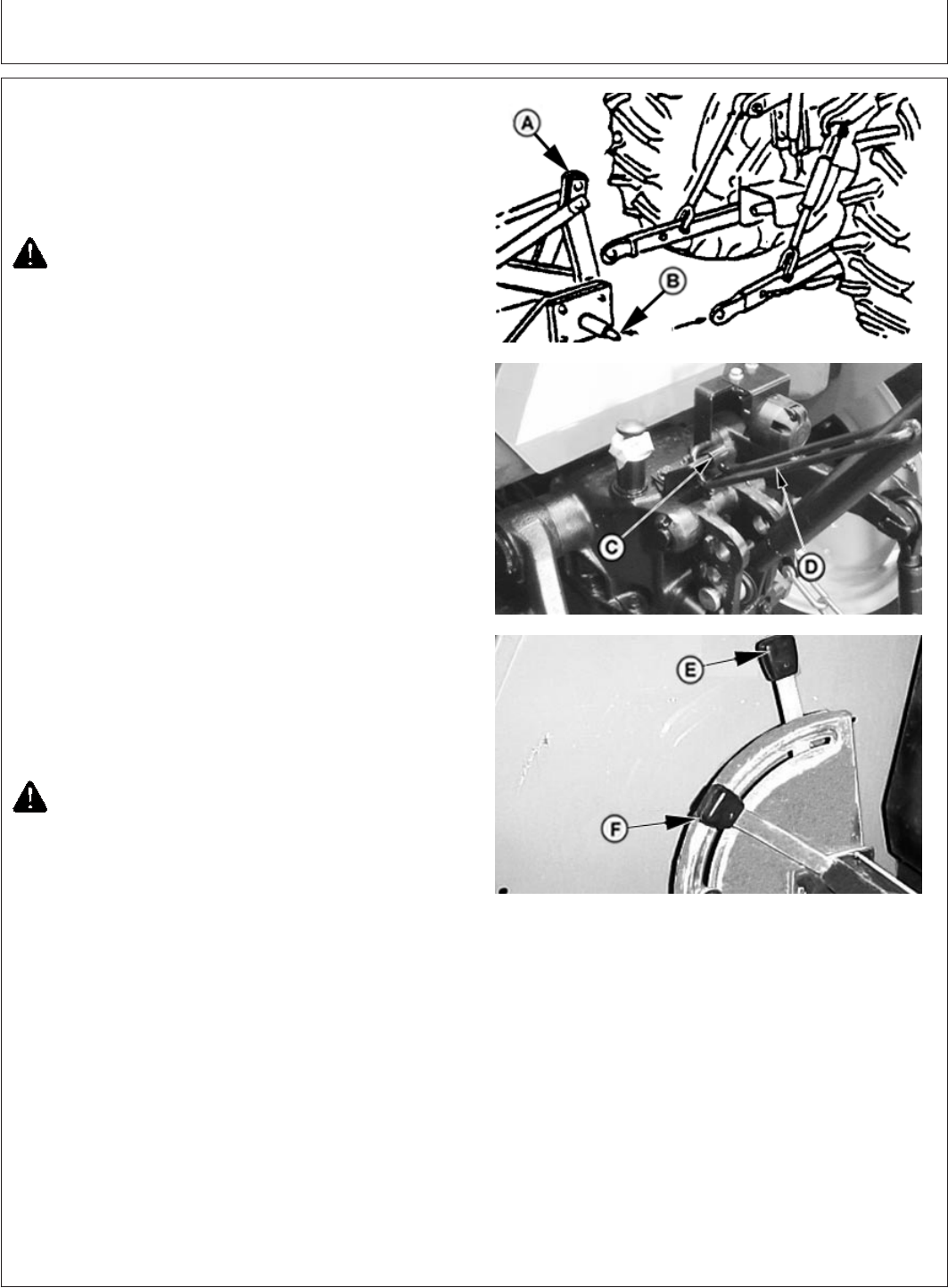
Attaching Implements to 3-Point Hitch
PY5374 –UN–09DEC05PY5375 –UN–09DEC05PY5376 –UN–11DEC05
A—Implement
B—Implement Hitch Pins
C—Center Link Locking Clip
D—Tab
E—Rockshaft Position Control Lever
F—Rockshaft Draft Control Lever
1. Be sure drawbar will not interfere. If necessary, move
drawbar ahead, or remove it. Check for any other
potential interference.
CAUTION: Prevent unexpected movement of
rockshaft by placing draft sensing lever in the
forward or OFF position before attaching
implement to hitch.
2. Back tractor up to implement (A) so hitch points (B)
align. Place transmission in neutral (N), stop the
engine and engage brakes BEFORE leaving the tractor
seat.
3. Slip draft links over implement hitch pins (B), and
retain with quick-lock pins.
NOTE: Locking pins can be stored on draft links (through
holes in sway chain ears) when not in use.
4. To remove center-link from transport hook, lift center
link locking clip (C), and rotate tab (D) to rear of center
link clip.
5. Attach center link to implement top mast.
6. Adjust center link and lift links as necessary. (See
Leveling the Hitch in this section.)
CAUTION: To avoid bodily injury or machine
damage whenever an implement, implement
quick coupler, or other attachment is connected
to the tractor 3-Point Hitch, check full range of
operation for interference, binding or PTO
separation.
7. Using rockshaft position control lever (E), lower and
raise implement slowly and check for any point of
interference.
55-8
022607
PN=61