


5
Minerals in the water or poor water quality can shorten the life of the steam generator or cause erratic
operation if the tank is not drained regularly. Drain the tank frequently. Jacuzzi Whirlpool Bath also strongly
recommends purchasing and installing the optional automatic drain down valve. The tank will be drained
automatically after each use after the water temperature lowers. Water filters and other conditioners are
strongly recommended if the water is of poor quality.
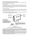
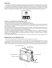
The Automatic Tank Drain Valve must be installed where the steam generator may be exposed to freezing
temperatures, e.g., in seasonal-use homes. (Water supply lines and water solenoid valve must not be allowed
to freeze.) This option prevents standing water from remaining in the tank. The tank will be automatically
drained through this valve when the water has cooled.
Read all warranty provisions before selecting a manual drain valve or the automatic drain down option.
Control and Temperature Sensor Cable Rough-in
A rough-in wiring kit is provided with unit to allow installer to locate and run wires to the temperature sensor
and digital controller before finish walls are installed.
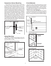
Control Cable Rough-in
The low voltage control can be mounted up to 25 feet from the generator either inside or outside the steam room.
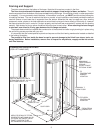
String the 25' cable from the generator through 1/2" holes in the wall studs or ceiling joists to the controller location.
Note: Do not staple through or damage cable. An option for tile rooms is to use the 1 gang rough-in box (provided)
and install at the desired control mounting location. A mounting plate with proper 2" diameter hole is included with the
control kit. Tile up to the 2" hole in the mounting plate.
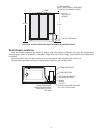
Temperature Sensor Rough-in
It is recommended that the sensor be mounted in the steam room 6" from the ceiling or below bottom of dome, but
not directly over the steam dispersion head or more than 7 feet above the floor. String the sensor cable from the sensor
location through 1/2" holes in the wall studs or ceiling joists to the generator location. Leave 12" of slack at the sensor
location. Note: Do not staple through or damage cable.
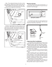
Leave a couple of feet of sensor and control cable free behind the steam generator to allow for removal
through access panel for maintenance or servicing if necessary.
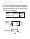
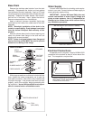
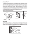
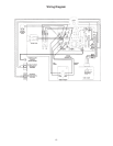
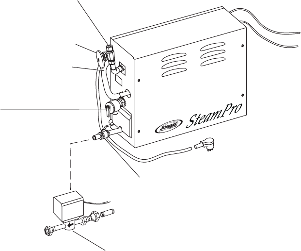
TANK DRAIN DOWN MANUAL VALVE (PROVIDED)
TO STEAM HEAD
(STEAM OUTPUT
FACTORY INSTALLED)
WATER SUPPLY
TO
TEMPERATURE
SENSOR
TO DIGITAL
CONTROLLER
NOTE: ALL COPPER PIPE SIZES ARE TO BE INDUSTRY NOMINAL SIZES
AND FITTINGS ARE NOT PROVIDED UNLESS OTHERWISE NOTED.
PRESSURE RELIEF VALVE
3/4 NPT (PROVIDED)
REDUCTION FROM 3/4 NPT
TO 1/2 NPT PERMITTED.
NOTE: PRESSURE RELIEF DRAIN LINE,
DRAIN LOCATION AND METHOD AS
REQUIRED BY LOCAL CODES. (TO BE
1/2 INCH MINIMUM SIZE COPPER)
MANUAL WATER
SUPPLY SHUTOFF
VALVE (PROVIDED)
NOTE: SITE DRAIN OR OTHER METHOD AS
REQUIRED BY LOCAL CODES. (WITH AUTOMATIC
DRAIN OPTION WATER DISCHARGED IS LESS
THAN 140°F.)
OPTIONAL AUTOMATIC
DRAIN VALVE