


10-31 109706 10/08
If the tractor creeps in the neutral position the control linkage may be adjusted as follows:
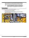
1. Raise and block the tractor up so the drive wheels are off of the floor.
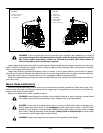
WARNING: Never work under the machine or attachment unless it is safely supported with jack
stands. Make certain machine is secure when it is raised and placed on the jack stands. The jack
stands should not allow the machine to move when the engine is running and the drive wheels are
rotating. Use only certified jack stands. Use only appropriate jack stands, with a minimum weight
rating of 2000 pounds to block the unit up. Use in pairs only. Follow the instructions supplied with the
vehicle stands.
2. Position the control lever in the neutral position. Disengage the deck clutch.
3. Start the engine and observe which way the wheels are rotating.
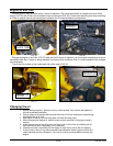
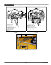
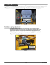
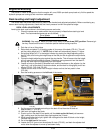
4. If wheel(s) are rotating forward, loosen the jam nuts on the pump linkage rods and
rotate the rod to lengthen the steering control linkage until the wheel(s) come to a stop
(FIG. 52). Repeat for the opposite side if necessary.
NOTE: The left linkage controls the left hydraulic pump and the right linkage
controls the right hydraulic pump.
5. If wheel(s) are rotating in reverse then loosen the jam nuts on the pump linkage rods
and rotate the rod to shorten the steering control linkage until the wheel(s) come to a
stop (FIG. 52). Repeat for the opposite side if necessary.
NOTE: The left linkage controls the left hydraulic pump and the right linkage
controls the right hydraulic pump.
6. When both wheels remain in neutral, tighten the jam nuts to lock the turnbuckle in place.
7. Test again by moving the control levers forward and backward before returning them to
the neutral position. If the tires are in neutral, the unit is now ready for operation.
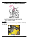
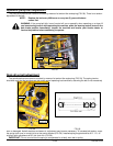
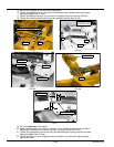
8. After adjusting for neutral it may be necessary to re-adjust the control lever stop
(FIG. 53).
Control lever stops
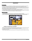
The control lever stops (FIG. 53) are designed to do two things: First, and most important, they must keep the
pumps from bottoming out internally. Secondly, the stops may be adjusted to help drive straight when the control levers
are pushed forward against the stops.
To keep the pumps from bottoming out internally use the following procedure:
1. To make the first adjustment the tractor engine must NOT be running.
2. Check to make sure the control levers are against the stops before the pumps are
bottomed out internally.
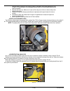
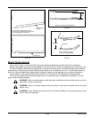
To do this, gently and slowly move the control levers forward and feel if there is some resistance on the pump lever
before the control levers hit the stops. Check one side at a time. If you sense that the pump arms are stopping the for-
ward motion of the control arms, loosen the jam nut on the adjustable stop of the corresponding side and turn the stop
(set screw) inward to stop the control levers slightly before the pump bottoms out. Lock in place when the adjustment is
correct by re-tightening the jam nut.
3. Do this for each side.
FIG. 52 FIG. 53
PUMP
ARM
PUMP LINKAGE
ROD
JAM NUT
STOP
CONTROL
LEVER
CONTROL
PANEL
JAM NUT