


10
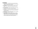
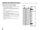
1. Remove the cover from junction box.
2. Strip
1
/2" off of each wire.
3. For all connections, route the wires through the conduit opening
inside the junction box.
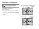
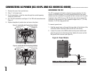
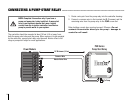
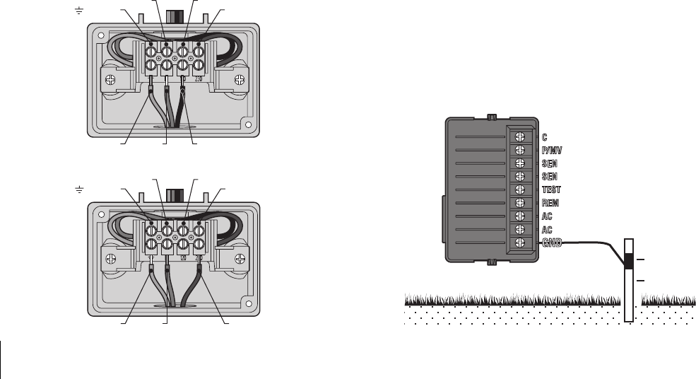
4. For 120 volt connections see Figure 3. For 230 volt connections see
Figure 4.
5. Replace faceplate of junction box and screw into place.
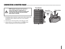
Clamp
Grounding
Electrode
Figure 5 Power Module
Green Wire
(Ground)
N Blue Wire (Neutral)
120 Black Wire (120 Volt)
Figure 3 – Junction Box with Terminal Strip (120 Volt)
Green Wire Blue Wire Black Wire
230 Brown Wire
(230 Volt)
Green Wire
(Ground)
N Blue Wire (Neutral)
Figure 4– Junction Box with Terminal Strip (230 Volt)
Green Wire Blue Wire Brown Wire
230 Brown Wire
(230 Volt)
120 Black Wire (120 Volt)
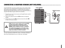
GROUNDING THE ICC
The ICC is equipped with built-in electrical surge protection. For this
system to function properly, the earth ground terminal on the power
module must be connected to a ground rod that is driven into the earth.
Important: Use a #10 (6 mm) or #8 (10 mm) bare wire to connect the
controller to the ground rod. Use a standard copper clad,
5
/8 " (1.6 cm)
diameter, 8' (2.5 m) long ground rod.
To connect ground wire:
1. Feed the ground wire up through the large hole at the bottom of the
controller cabinet (the same hole used for the valve wires).
2. Loosen the screw on the GND terminal on the power module and
place the ground wire into the terminal. Tighten the screw so that
the ground wire is secure (see Figure 5).
CONNECTING AC POWER (ICC-801PL AND ICC-800M/ICC-800SS) ..............................