


8
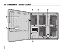
CONNECTING VALVES ............................................................................................................
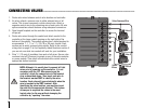
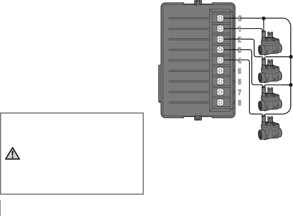
Valve Common Wire
Valve 4
Valve 3
Valve 2
Valve 1
Valve
Wires
1. Route valve wires between control valve location and controller.
2. At valves, attach a common wire to either solenoid wire of all
valves. This is most commonly a white colored wire. Attach a
separate control wire to the remaining wire of each valve. All wire
splice connections should be done using waterproof connectors.
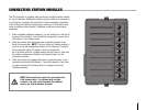
3. Open hinged faceplate on the controller to access the terminal
strip area.
4. Route valve wires through the conduit and attach conduit to the
controller at the large conduit opening on the right side of the
bottom of the cabinet. The conduit opening has a triple knockout to
accommodate 1", 1
1
/4" or 1
1
/2" (25, 32 or 40 mm) conduit. Each
section can be easily removed using a knife. Refer to the conduit
sizing chart on page 31 in the Frequently Asked Questions section if
you are not sure what size conduit will work for your installation.
5. Strip
1
/2" (13 mm) of insulation from ends of all wires. Secure valve
common wire to C (Common) terminal on any of the valve modules
or power module. Then attach all individual valve control wires to
appropriate station terminals.
NOTE: Although it is usually best to connect all field
wires prior to powering up the controller, it is not
necessary with the ICC. After powering up the
controller, attach the common wire to the terminal
strip as described above. Then touch each wire to
the terminal marked TEST to identify the valve
location. Each valve will open electrically when the
wire is touched to the TEST terminal. After
identifying the valve location, you may then insert
the wire into the appropriate terminal. This feature
allows you to sequence the valves in the most
logical order for the user without damaging the
controller by “sparking” the wires.