


Page 11
August 20, 2008
BODEGA BAY WOOD INSERT
R
435-1320B
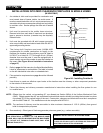
INSTALLATION IN CANADA
MASONRY and HEAT-CIRCULATING
(INSTALLATIONS INTO FACTORY-BUILT FIREPLACES ARE PROHIBITED IN CANADA)
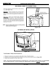
Whether installed in a masonry or heat-circulating replace, this replace insert must be installed with a continuous chim-
ney liner of six inch (152mm) diameter extending from the replace insert to the top of the chimney. The chimney liner must
conform to the Class 3 requirements of CAN/ULC-S635, Standard for Lining Systems for Existing Masonry or Factory-Built
Chimneys and Vents, or CAN/ULC-S640, Standard for Lining Systems for New Masonry Chimneys.
• Do not remove bricks or mortar from replace to accommodate insert.
• The face of the replace must be sealed to prevent room air passage into the chimney cavity.
• The permanent metal warning label provided must be afxed to the back of the replace with screws or nails
to the replace, in a location readily visible should the replace insert by removed, stating that the replace may
have been altered to accommodate the insert, and must be returned to original condition for use as a conventional
replace.
• Circulating air chambers may not be blocked.
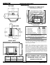
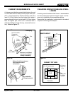
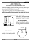
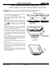
Leveling Bolts
Sheet Metal Shims
Place under leveling bolts
and slide insert into place
Leveling Bolt
Reach between side of insert and outer skin
cut-out view
The insert is shipped with 2 leveling bolts and 2 sheet metal
guides for ease in sliding the insert into place when using the
leveling bolts. Not all installations will require the use of the
leveling bolts. The sheet metal guides are used only when
the leveling bolts are necessary. Discard if not needed.
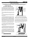
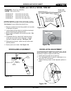
ADUSTING THE LEVELING BOLTS
I
t is best to use a 1/2” (12.7mm) socket wrench with an
extended handle for ease in adjusting bolts to the desired level.
The bolts will adjust from 0 inches to 2 inches (0 - 51mm). You
can also reach in and adjust the bolts by hand, although space
is limited. See Figure 11A.
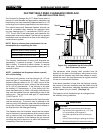
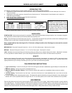
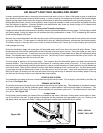
LEVELING BOLTS AND SHEET METAL SHIMS
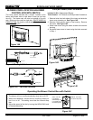
SHEET METAL GUIDES
Slide each guide under the insert on each side placing
them directly under leveling bolts. If they are not directly
under the bolts, the bolts may hang up on uneven material
when sliding the insert into place. See Figure 11B.
Figure 11A
Figure 11B