


Page 10SKU 93920
For technical questions, please call 1-800-444-3353.
(44) under the base and over the Bolt at each Floor Plate (16) connection. Use
Long Bolts (60) for the Rear Brace (23) connections.
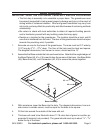
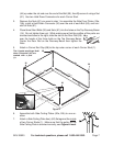
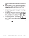
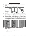
Attach the tops of the Rear Studs (8, 9, & 10) to the Rear-Right and Rear-Left Crown
Beams (4, 5). For the Rear-Center Stud (10), use a
Top Center Connector (39) to connect to the Crown
Beams, as shown to the right.
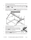
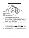
Refer to the Note in Figure C. Attach the two Side
Studs (12) in the center of each side (without asterisks
in Figure C) to the outside of the frame. Make the
bottom connections using a Long Bolt (60) for later
assembly of the Side Diagonal Brace (22). Slide a
Hold-Down Connector (44) under the base and over the Long Bolt at each bottom
connection, but do not install a Nut (61) over the Long Bolt yet.
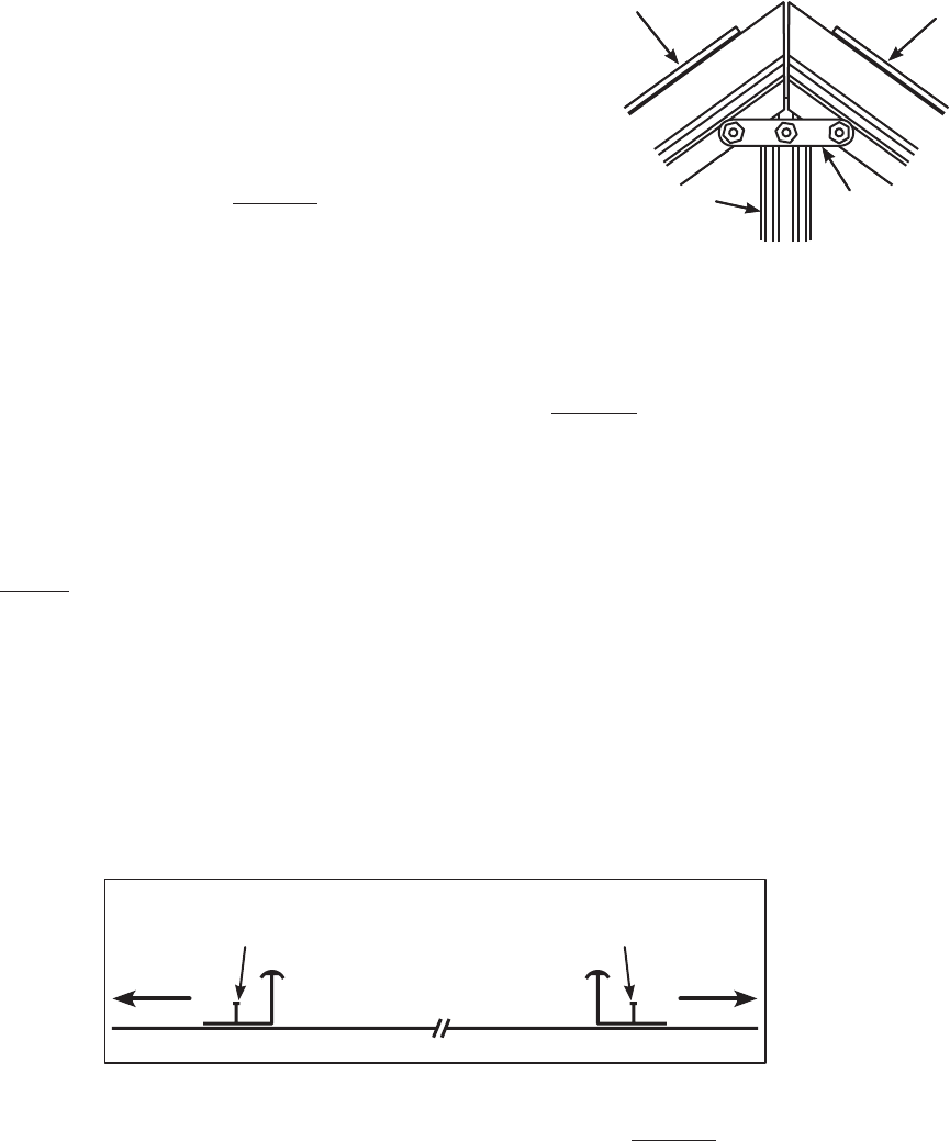
Refer to the Note in Figure C. Attach the two Side Studs (12) near the corner of
each side (with asterisks (*) in Figure C) to the outside of the frame. Slide a Long
Bolt (60) into each slot for later Side Diagonal Brace (22) assembly. Slide a Hold-
Down Connector (44) under the base and over the Bolt before installing the Nut
(61) at each bottom connection.
Attach a Side Diagonal Brace (22) to the lower hole of a Corner Stud (1) on the
inside with the TOP arrow pointing towards the Corner Stud as shown in Figure
C. Use a Long Bolt (60) to attach the Brace. Attach the other three Side Diagonal
Braces (22) to the other Corner Studs (1) in the same manner.
Attach the center hole of each Brace to the Long Bolt (60) in the center of the Side
Studs (12) designated with an asterisk (*) in Figure C. This Bolt (60) was included
in step 4, above.
Attach the bottoms of all four Side Diagonal Braces (22) to the Long Bolts (60)
installed at the bottoms of the remaining Side Studs.
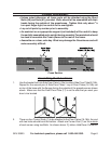
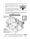
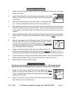
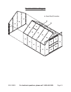
View from above
to
Corner
Stud (1)
Left
Doorway
Stud (6)
Front Floor Plate (17)
to
Corner
Stud (1)
Right
Doorway
Stud (7)
Install the Left and Right Doorway Studs (6 & 7) to the outside of the frame so that
they rest flat against the frame. Their orientation should be the same as shown
above. Slide a Long Bolt (60) into each slot for later Front Brace (21) assembly.
Make the bottom connections using a Long Bolt (60) for later assembly of the Front
Diagonal Braces (24). Slide a Hold-Down Connector (44) under the base and over
2.
3.
4.
5.
6.
7.
8.
3910
4 5
3910
4 5