


Generac
®
Power Systems, Inc. 7
Section 2 – Operation
QUIETPACT 55, 65, and 75 Recreational Vehicle Generators
Crankcase and oil filter capacity is approximately 1.8
L or 1.9 U.S. quarts. DO NOT use special additives.
See Sections 3.1 and 3.2 for oil level check and filling
procedures.
1.6.4 ENGINE SPECIFICATIONS
Type of Engine
QUIETPACT 55/65/75 ................................................GT-760
Cooling Method ........................................................Air-cooled
Rated Horsepower
QUIETPACT 55..............................................27 at 3600 rpm
QUIETPACT 65..............................................27 at 3600 rpm
QUIETPACT 75..............................................27 at 3600 rpm
Displacement
QUIETPACT 55/65/75....................................................760cc
Compression Ratio........................................................8.6 to 1
Cylinder Block ..........................Aluminum w/Cast Iron Sleeve
Type of Governor ..............................Mechanical, Fixed Speed
Engine Governor Speed
QUIETPACT 55 ......................................................2200 rpm
QUIETPACT 65/75..................................................2571 rpm
Air Cleaner ........................Paper Element w/Foam Precleaner
Starter ........................................................12-volt DC Electric
Ignition System ......................Solid-state w/Flywheel Magneto
Recommended Spark Plug
Champion ..................................................................RC14YC
AC....................................................................................R45S
Fram Autolite ......................................................................65
Spark Plug Gap........................................0.030 inch (0.8 mm)
Recommended Min. Battery............400 Cold Cranking Amps
1.6.5 EMISSIONS COMPLIANCE PERIOD
For nonhandled engines the Emissions Compliance
Period referred to on the Emissions Compliance
Label indicates the number of operating hours for
which the engine has been shown to meet Federal
emission requirements.
• For engines less than 225 cc displacement,
Category C=125 hours, B=250 hours, and A=500
hours.
• For engines of 225 cc or more, Category C=250
hours, B=500 hours, and A=1000 hours.
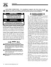
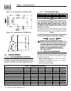
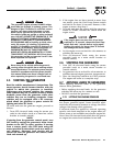
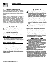
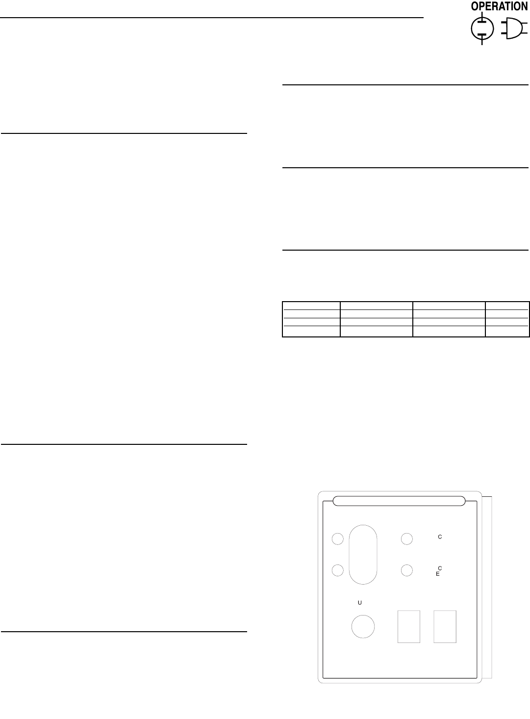
2.1 GENERATOR CONTROL PANEL
The following features are mounted on the generator
control panel (Figure 2.1):
2.1.1 FUEL PRIMER
Before starting a cold engine (if it has not been start-
ed in more than two weeks), press this switch for
approximately ten seconds to bring fuel from the
tank to the fuel pump. This rocker type switch
springs back into its original position when it is
released.
2.1.2 START/STOP SWITCH
To crank and start the engine, hold this switch in the
START position. Release the switch when the engine
starts. To stop an operating engine, press and hold
the switch in the STOP position until the engine shuts
off. The switch center position is the RUN position.
2.1.3 7.5 AMP FUSE
The fuse protects the engine’s DC control circuit
against electrical overload. If the fuse element has
melted open due to overloading, the engine cannot be
cranked. If the fuse must be replaced, use only an
identical 7.5 amp replacement fuse.
2.1.4 LINE BREAKERS
Protects generator’s AC output circiut against
overload, i.e., prevents unit from exceeding
wattage/amperage capacity. The circuit breaker rat-
ings are as follows:
NOTE:
If this generator has been reconnected for dual
voltage AC output (120/240 volts), install line
breakers having an amperage rating that is differ-
ent than that stated above. The replacement line
breakers consist of two separate breakers with a
connecting piece between the breaker handles (so
that both breakers will operate at the same time).
If the unit is reconnected for dual voltage, it is no
longer RVIA or CSA listed.
Figure 2.1 – Typical Control Panel
P
R
I
M
E
S
T
O
P
S
T
A
R
T
F
U
E
L
F
S
E
7
.
5
A
0
E0580 REV. B
CO
NTR
O
L
C
ENTE
R
C
I
R
U
I
T
B
R
E
A
K
E
R
B
R
A
K
E
R
C
I
R
U
I
T
PRE
SS
PRIME
S
WIT
C
H F
O
R 1
0
S
E
CO
ND
S
BEFORE STARTING. WHEN STARTING
,
DO NOT PRESS
S
TART B
U
TT
O
N L
O
N
G
ER THEN 1
5
S
E
CO
ND
S
PER ATTEMPT
.
IF
G
ENERAT
O
R D
O
E
S
N
O
T
S
TART
.
REM
O
VE AND IN
S
PE
C
T F
US
E
.
(
SEE OWNER'S MANUAL TROUBLE SHOOTING GUIDE.
)
◆
◆
◆
◆
◆
◆
Model Circuit Breaker 1 Circuit Breaker 2 240 Volt
QuietPact 55 30A 20A 25A 2P
QuietPact 65 30A 30A 30A 2P
QuietPact 75 35A 35A 35A 2P