


Generac
®
Power Systems, Inc. 23
• If the generator cannot be bolted directly to
the supporting frame or support tubing, consider
using additional tubing, angle brackets or other
supports to give the supporting frame sufficient
strength.
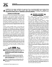
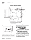
6.1.3 SUSPENDED MOUNTING
If planning to suspend the generator below the hori-
zontal support tubing, the suspension method to use
with the vehicle frame members must (a) be able to
support the weight of the generator AND (b) provide
sufficient restraint for the generator. One typical sus-
pended mounting system is shown in Figure 6.2. The
location of a suspended mounting system must be
carefully planned, keeping the following general rules
in mind:
• Protect the generator against road splash and
debris. Baffles or splash guards may be required
to protect certain areas of the generator. To make
sure the generator is adequately protected, road
test the installation through mud, water and slush.
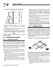
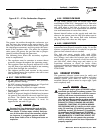
Figure 6.2 – Typical Suspended Mounting
System
• The installer must make certain that the selected
location will permit adequate cooling and ventilat-
ing airflow to be supplied.
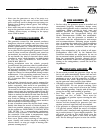
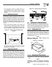
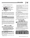
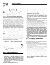
6.1.4 GENERATOR RESTRAINT
Use four 3/8"-16 hardened steel bolts (Grade 5) to
fasten the generator to the supporting frame or the
support tubing. These bolts must pass through (a)
the generator mounting base, (b) the compartment
floor (if a compartment is used) and (c) the support-
ing framework (Figure 6.3). All bolts must be long
enough so that when tight, at least three threads are
visible past the retaining lock nuts. Refer to Section
6.2 for the location of the generator mounting holes.
Figure 6.3 – Typical Generator Restraint
6.2 GENERATOR COMPARTMENTS
Whether the generator set is being installed inside a
compartment specifically manufactured to house a gen-
erator or inside a compartment that the installer con-
structs, the compartment MUST meet certain specifi-
cations as outlined in the following sections:
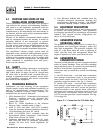
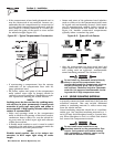
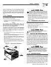
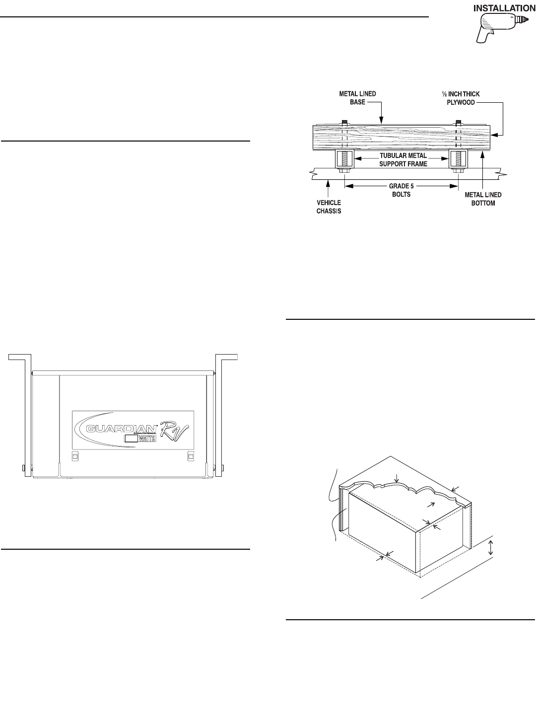
6.2.1 COMPARTMENT SIZE
Plan the compartment size carefully. Provide a mini-
mum clearance of 1/2 inch (13 mm) on the front and
top, 1 inch (25 mm) on the sides, and 1/2 inch (13
mm) from the back for air circulation AFTER the
compartment has been lined with metal and sound
insulation (Figure 6.4).
NOTE:
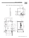
Refer to “Figure 5.2 – Major Features and
Dimensions” on page 21.
Figure 6.4 – Clearances
6.2.2 COMPARTMENT CONSTRUCTION
• The generator compartment should be either con-
structed of, or lined with, 26-gauge galvanized
steel.
NOTE:
Aluminum is NOT an acceptable alternative
to galvanized steel due to aluminum’s low melting
point.
◆
1" Clearance
in Back
1/2" Clearance on Top
1" Each Side
1/2"
in Front
Insulation
Plywood
Compartment
18" Clearance Recommended
Below (Minimum 12")
◆
◆
◆
Section 6 – Installation
QUIETPACT 55, 65, and 75 Recreational Vehicle Generators