


Generac
®
Power Systems, Inc. 27
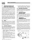
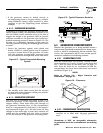
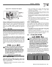
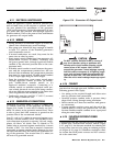
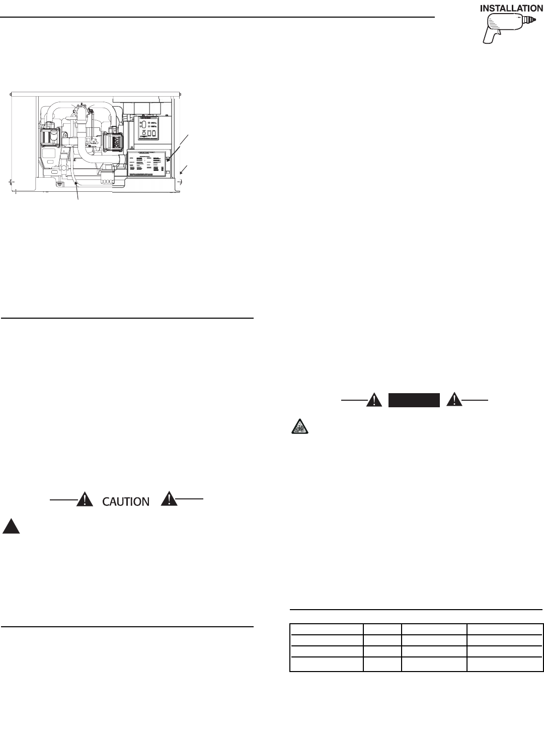
Figure 6.10 – Generator Fuel System
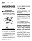
Factory installed generator fuel system components
include (a) fuel filter, (b) 12-volt DC electric pump, (c)
engine carburetor, and (d) interconnecting lines and
fittings. Connect a fuel supply line to the fuel filter
inlet. Use a flexible length of approved fuel hose
between the fuel filter inlet connection and rigid fuel
lines.
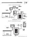
6.4.1 FUEL TANK
Either the generator must share the vehicle engine's
fuel tank, or a separate fuel tank for the generator set
must be installed. All fuel tanks installed on the vehi-
cle must be constructed, installed and restrained so
they comply with applicable codes, standards and
regulations.
If the generator is to share the vehicle engine's tank,
separate fuel pickup tubes are required for the engine
and the generator. Generac recommends that the fuel
pickup tube be two to three inches (51 to 76 mm)
shorter than the vehicle engine's pickup tube. This
prevents the generator from depleting the entire fuel
supply during prolonged generator operating peri-
ods.
Do NOT tee the generator fuel supply line into
the vehicle engine fuel supply line. If this is
done, the generator will be starved of fuel
when both engines are operating at the same
time. Also, while the vehicle engine is not run-
ning, generator operation may drain the vehi-
cle engine supply line, making it difficult to
start the vehicle engine.
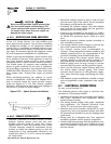
6.4.2 GENERATOR FUEL SUPPLY LINE
6.4.2.1 Rigid Fuel Lines
Those lines used to supply fuel from a tank to the
generator must comply with applicable codes, stan-
dards and regulations. The following general rules
apply to rigid fuel lines:
• Rigid lines should be of annealed, seamless, drawn
aluminum or steel.
• Lines and fittings must comply with SAE J512F,
“Standard Automotive Fittings,” or with ANSI
B126.26 (latest edition).
• Route the fuel line so that at least 2 inches (51 mm)
of clearance is maintained between the line and
any exhaust system parts.
• Do not attach electrical wiring to fuel lines. Route
the wiring so it cannot come into contact with any
fuel line.
• Route fuel lines so if they leak, fuel does not drip
onto any electrical or exhaust system parts.
• Use nonferrous metal straps without sharp edges
to secure fuel lines.
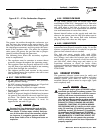
6.4.2.2 Flexible Fuel Line
Use an approved flexible length of fuel hose between
the generator fuel inlet connection and rigid fuel
lines. This prevents breaking of the line caused by
vibration, shifting, settling or movement. The follow-
ing rules apply:
• The flexible hose must comply with SAE J30B,
“Standard for Fuel and Oil Hose.” It must be
approved for use with gasoline.
• The hose should be at least 6 inches (152 mm)
longer than is needed to prevent the hose from
rupturing if the generator shifts or settles.
6.5 LP GAS FUEL SYSTEM
LP gas is highly EXPLOSIVE. The gas is heavier
than air and tends to settle in low areas. Even
the slightest spark can ignite it and cause and
explosion. Only competent, qualified people
should be allowed to install, test, adjust or ser-
vice an LP gas fuel system. Install the optional
fuel system in compliance with applicable
codes, standards and regulations. After the
installation, do not do anything that might ren-
der the system in noncompliance with applica-
ble codes and standards.
The LP powered range of generators are fitted with a
nonadjustable, factory set system. These systems are
tamper-proof to meet 1997 California Air Resources
Board requirements for engine emission.
6.5.1 LP FUEL CONSUMPTION (LB./HOUR)
◆
DANGER
◆
!
◆
Fuel Pump
(Behind Access
Cover)
Fuel Filter
(Side of Unit)
Fuel Line
Section 6 – Installation
QUIETPACT 55, 65, and 75 Recreational Vehicle Generators
Model Idle 50% Load 100% Load
Quietpact 55LP 2.34 3.96 5.07
Quietpact 65LP 2.34 4.20 6.50
Quietpact 75LP 2.34 4.44 8.75