


34 Generac
®
Power Systems, Inc.
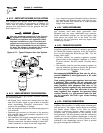
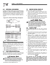
6.9 OPTIONAL ACCESSORIES
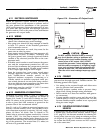
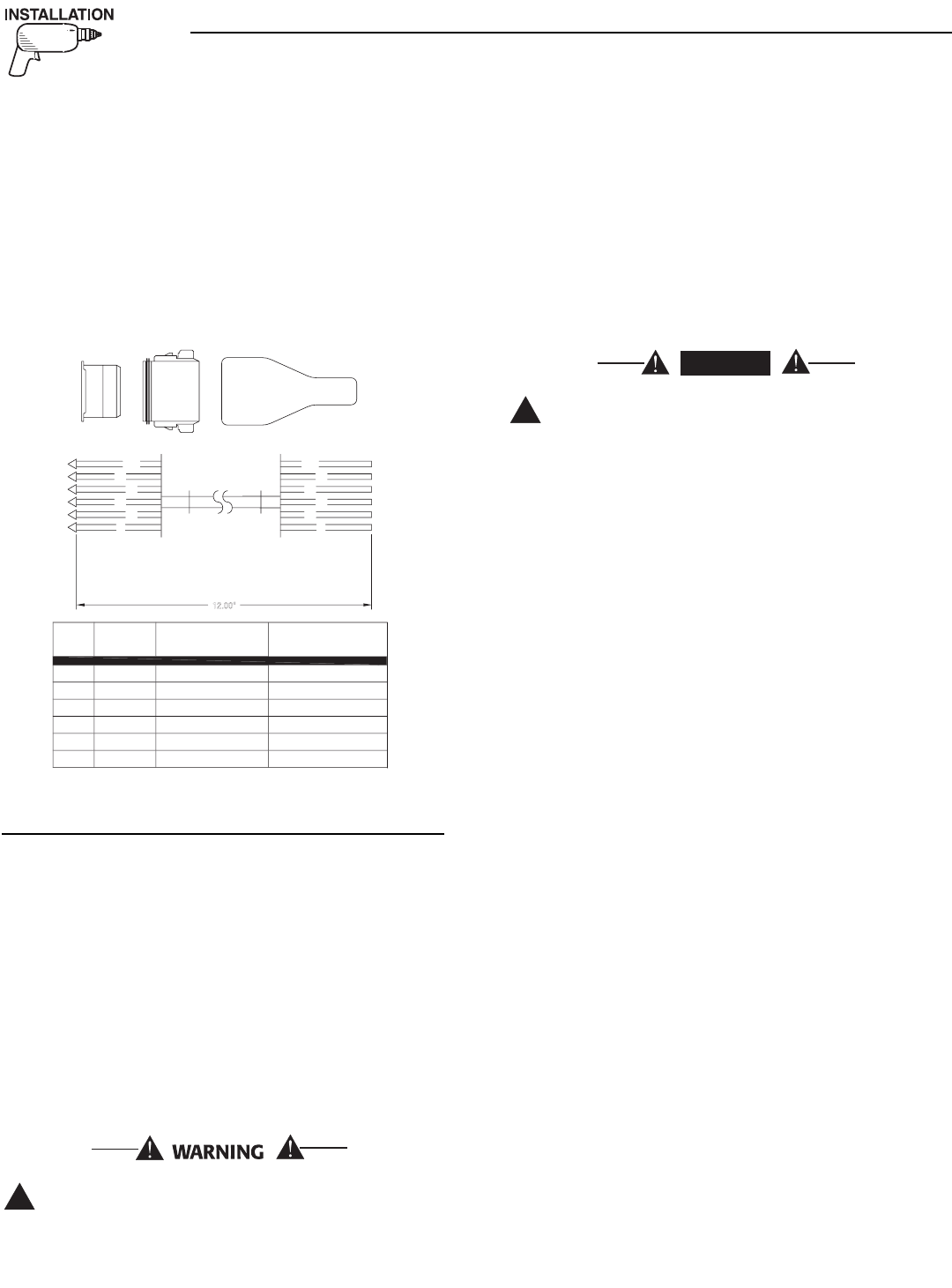
A plug-in receptacle (Figure 6.18) is provided on the
generator set, above the muffler enclosure. Use this
receptacle to connect an optional remote-mounted
start/stop panel to the generator. Installation of such
a panel will permit starting and stopping the genera-
tor engine from any convenient location inside the
vehicle.
Figure 6.18 – Remote Panel Plug-in Receptacle
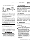
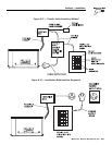
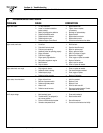
6.9.1 REMOTE PANEL MODELS
The remote panels mount a rocker type start/stop
switch, a “Generator Run” advisory lamp and an
hourmeter. The hourmeter should be used in con-
junction with the maintenance operations found in
Part I of this manual.
• Part number 0F0429 includes the remote panel
and a 10 foot long, 6 wire harness.
• Part number 0F0430 includes the remote panel
and a 30 foot long, 6 wire harness.
7.1 POST INSTALLATION TESTS
The air-cooled generator set was factory tested and
adjusted. It should not be necessary to adjust the unit
any further except under special circumstances.
Do not make any unnecessary adjustments.
Factory settings are correct for most applica-
tions. When making adjustments, however, be
careful to avoid overspeeding the engine.
7.2 BEFORE INITIAL START-UP
Before starting, complete the following:
1. Check the engine crankcase oil level and, if nec-
essary, fill to the dipstick “FULL” mark (cross-
hatched area) with the recommended oil. Do not
fill above the FULL mark.
2. Check the fuel supply. Gas fuel lines must have
been properly purged and leak tested in accor-
dance with applicable fuel codes. All fuel shutoff
valves in the fuel supply lines must be open.
If a liquid propane (LP) gas fuel system has
been installed, it must be properly tested for
leaks before operating the system in compli-
ance with ANSI A119.2/NFPA 501C. No leakage
is permitted. Be sure that gasoline fuel vapors
do not enter the vehicle interior.
7.3 INITIAL START
When certain that the unit has been properly
installed and prepared for use, start the engine as fol-
lows:
1. Turn off all electrical loads. Do this by setting the
generator’s main circuit breakers to their “OFF”
(or open) position.
2. Refer to Part I, Section 2.5, “Starting the
Generator”, for cranking and starting instruc-
tions. The engine may require more cranking for
initial starting since the fuel lines have to be
primed (use of the primer switch will shorten this
time).
3. Let the engine warm up for about five minutes to
allow internal temperatures to stabilize.
4. Carefully inspect the engine/generator for fuel, oil
and exhaust system leaks. Before proceeding to
the next step, correct any leakage immediately.
5. When all tests and adjustments at no-load are
completed, apply electrical loads and check for
proper operation under load. See Section 7.4.
Run the unit at least 30 minutes with loads
applied.
6. Turn off all electrical loads by setting the genera-
tor’s main circuit breakers to their “OFF” (or
open) position.
7. Let the unit run at no-load for a few minutes to
stabilize internal engine/generator temperatures.
Then, shut down the engine.
NOTE:
The generator set was thoroughly tested and
adjusted at the factory before shipping. No addi-
tional adjustment should be necessary. Only qual-
ified service technicians who have been trained
should perform adjustments outlined in this man-
ual.
!
DANGER
!
◆
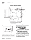
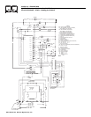
12.00"
14
0
17
1
5
1
8
14A
1
3
2
5
4
6
0
14
17
1
8
14A
1
5
1
5
17
14A
1
8
14
0
N
o.
WIRE
WIRE
CO
L
OR
RED
YELL
OW
O
RAN
GE
WHITE
BL
UE
BR
O
W
N
12.0
(
305
)
LENGTH
(
mm
)
12.0
(
305
)
12.0
(
305
)
12.0
(
305
)
12.0
(
305
)
12.0
(
305
)
FUNCTION
GROUND
ENGINE RUN SIGNAL
12 VDC
START
STOP
PRIME
P
/
N:
0
D
9099
-
B
Section 7 – Post Installation
QUIETPACT 55, 65, and 75 Recreational Vehicle Generators