


30
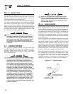
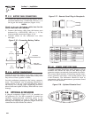
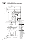
2.7.3 BATTERY CABLE CONNECTIONS
1. Connect the battery cable from the battery post or
terminal indicated by a POSITIVE, POS or (+) to
the lug on the starter contactor (Figure 2.16).
NOTE:
Check to be sure the battery cable boot for the
starter cable has been installed.
2. Connect the battery cable from the battery post
indicated by a NEGATIVE, NEG or (-) to the
frame ground connection (Figure 2.16).
3. Connect cables so the connectors are clean
and tight.
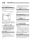
Figure 2.16 – Connecting Battery Cables
3
42.
2
[13 1/2"]
77
8
.
9
[
30 11/16"
]
REF.
FR
O
NT D
OO
R A
CC
E
SS
F
OR
ALL RE
Q
UIRED MAINTENANC
E
REM
O
TE PANE
L
CO
NNE
C
T
OR
500
.
2
[
19 11/16"
]
REF.
A
C
OU
TP
UT
HARNE
SS
H
O
T AI
R
EXHA
UST
TAIL PIPE
EXIT
O
IL DRAI
N
AIR
INTAKE
4
8
.
1
[
1 7/8"
]
222.7
[
8 3/4"
]
300
.
7
[
11 13/16"
]
369
.
7
[
14 9/16"
]
688
.
3
[
27 1/8"
]
2
9
[
1 1/8"
]
55
.
5
[
2 3/16"
]
3
7
6
.
5
[14 13/16"]
5/
1
6
"-1
8
WELDN
U
T
S
(
6 PLACES
)
8
2.
5
[
3 1/4"
]
3
4
3
.
4
[
13 1/2"
]
42
3
.
2
[
16 11/16"
]
717.7
[
28 1/4"
]
50
.
8
[
2"
]
11
8
[
4 5/8"
]
22
3
.
5
[8 13/16"]
60
[
2 3/8"
]
21
0
[8 1/4"]
17
6
.
6
[6 15/16"]
83
.
5
[
3 5/16"
]
42
9
.
5
[16 15/16"]
414.
5
[16 5/16"]
360
.
5
[14 3/16"]
63
.
5
[
2 1/2"
]
41
6
[16 3/8"]
17
0
[6 11/16"]
7
9
[
3 1/8"
]
1
01
[4"]
TYP.
6
.
7
[
1/4"
]
7
36
.
4
[
29"
]
47
6
.
4
[18 3/4"]
36
.
5
[1 7/16"]
[1 7/16
[1 7/16
39
.
6
[
1 9/16"
]
69
.
6
[
2 3/4"
]
3
4.
3
[
1 3/8"
]
71.2
[
2 13/16"
]
211.
3
[8 5/16"]
NE
G
. BAT
.
CO
NNE
C
TI
ON
P
OS
. BAT
.
CO
NNE
C
TI
ON
LP F
U
EL INLE
T
VIEW FR
O
M T
OP
N
O
TE: ALL AIR INTAKE
S
AND EXHA
US
T
OU
TLET
S
M
US
T B
E
KEPT
C
LEAR
O
F ANY
O
B
S
TR
UC
TI
O
N
S
. ALL
O
PEN ARE
A
IS RE
Q
UIRED FOR COOLING
.
CO
NNE
C
TI
O
N
S
IN
BA
C
K
O
F
G
ENERAT
OR
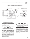
2.7.4 BATTERY COMPARTMENT
Install the generator battery in its own, vented com-
partment. Place the battery compartment away from
any source of heat, sparks or flame.
Provide ventilation openings in the battery compart-
ment. The minimum size of openings should be 2
square inches at the top of the compartment. Mount
the battery on a strong, rigid supporting structure,
where leaks and spills of battery fluid will not cause
damage.
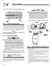
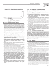
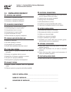
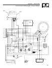
2.8 OPTIONAL ACCESSORIES
A plug-in receptacle (Figure 2.17) is provided on
the generator set. Use this receptacle to connect an
optional remote-mounted start/stop panel to the
generator. Installation of such a panel will permit
starting and stopping the generator engine from any
convenient location inside the vehicle.
Figure 2.17 – Remote Panel Plug-in Receptacle
12.00"
14
0
17
1
5
1
8
14A
1
3
2
5
4
6
0
14
17
1
8
14A
1
5
1
5
17
14A
1
8
14
0
N
o.
WIRE
WIRE
CO
L
OR
RED
YELL
OW
O
RAN
GE
WHITE
BL
UE
BR
O
W
N
12.0
(
305
)
LENGTH
(
mm
)
12.0
(
305
)
12.0
(
305
)
12.0
(
305
)
12.0
(
305
)
12.0
(
305
)
FUNCTION
GROUND
ENGINE RUN SIGNAL
12 VDC
START
STOP
PRIME
P
/
N:
0
D
9099
-
B
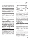
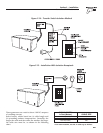
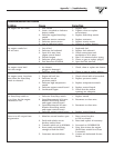
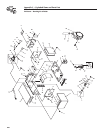
2.8.1 REMOTE START/STOP PANEL
A remote mounted Start/Stop panel (Figure 2.18) is
available that allows the user to start and stop the
generator engine conveniently from inside the vehicle.
The remote panel includes a Start/Stop switch, hour-
meter, generator run lamp, a fuel prime switch, and
a wire harness. The hourmeter should be used in
conjunction with the maintenance operations found
in Part I of this manual.
Figure 2.18 – Optional Remote Panel
PRIME
F
U
E
L
S
T
OP
R
UN
Section 2 – Installation
Recreational Vehicle Generator