


28
• Conductors must be rated 221° F (105° C) or must
be of a larger conductor size.
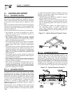
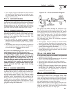
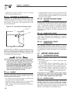
2.6.3 GENERATOR AC CONNECTIONS
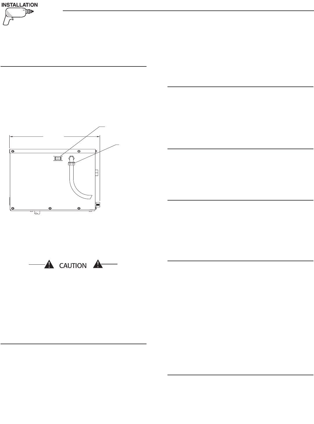
Generator AC output leads (BLACK) “hot” and
(WHITE) grounded neutral come out of the generator
as shown in Figure 2.13. There is also a green lead
that connects to ground in the junction box of the
recreational vehicle.
Figure 2.13 – Generator AC Output Leads
3
42.
2
[13 1/2"]
77
8
.
9
[
30 11/16"
]
REF.
FR
O
NT D
OO
R A
CC
E
SS
F
OR
ALL RE
Q
UIRED MAINTENANC
E
REM
O
TE PANE
L
CO
NNE
C
T
OR
500
.
2
[
19 11/16"
]
REF.
A
C
OU
TP
UT
HARNE
SS
H
O
T AI
R
EXHA
UST
TAIL PIPE
EXIT
O
IL DRAI
N
AIR
INTAKE
4
8
.
1
[
1 7/8"
]
222.7
[
8 3/4"
]
300
.
7
[
11 13/16"
]
369
.
7
[
14 9/16"
]
688
.
3
[
27 1/8"
]
2
9
[
1 1/8"
]
55
.
5
[
2 3/16"
]
3
7
6
.
5
[14 13/16"]
5/
1
6
"-1
8
WELDN
U
T
S
(
6 PLACES
)
8
2.
5
[
3 1/4"
]
3
4
3
.
4
[
13 1/2"
]
42
3
.
2
[
16 11/16"
]
717.7
[
28 1/4"
]
50
.
8
[
2"
]
11
8
[
4 5/8"
]
22
3
.
5
[8 13/16"]
60
[
2 3/8"
]
21
0
[8 1/4"]
17
6
.
6
[6 15/16"]
83
.
5
[
3 5/16"
]
42
9
.
5
[16 15/16"]
414.
5
[16 5/16"]
360
.
5
[14 3/16"]
63
.
5
[
2 1/2"
]
41
6
[16 3/8"]
17
0
[6 11/16"]
7
9
[
3 1/8"
]
1
01
[4"]
TYP.
6
.
7
[
1/4"
]
7
36
.
4
[
29"
]
47
6
.
4
[18 3/4"]
36
.
5
[1 7/16"]
[1 7/16
[1 7/16
39
.
6
[
1 9/16"
]
69
.
6
[
2 3/4"
]
3
4.
3
[
1 3/8"
]
71.2
[
2 13/16"
]
211.
3
[8 5/16"]
NE
G
. BAT
.
CO
NNE
C
TI
ON
P
OS
. BAT
.
CO
NNE
C
TI
ON
LP F
U
EL INLE
T
VIEW FR
O
M T
OP
N
O
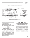
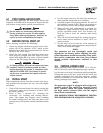
TE: ALL AIR INTAKE
S
AND EXHA
US
T
OU
TLET
S
M
US
T B
E
KEPT
C
LEAR
O
F ANY
O
B
S
TR
UC
TI
O
N
S
. ALL
O
PEN ARE
A
IS RE
Q
UIRED FOR COOLING
.
CO
NNE
C
TI
O
N
S
IN
BA
C
K
O
F
G
ENERAT
OR
Leads BLACK to WHITE are protected against over-
load by a 30-amp circuit breaker (CB1). Use this
line-to-neutral connection separately to operate 120-
volt, single-phase, 60 Hertz, AC loads requiring up to
3,400 watts (3.4 kW) of power.
Do NOT connect electrical loads in excess of any
circuit breaker rating or probems will develop
with circuit breaker tripping, which causes a loss
of AC output. Also, do NOT exceed the gener-
ator's rated wattage capacity. Add the watts
or amperes of all lighting, appliance, tool and
motor loads the generator will operate at one
time. This total should be less than the unit's
rated wattage/amperage capacity.
2.6.4 CONDUIT
Route the connections between the generator and the
junction box through approved, flexible conduit. The
following general rules apply:
• Cut wiring to the required length and allow extra
wire for junction box connections.
• Carefully prepare conduit ends to prevent sharp
edges from cutting through wiring insulation.
• Route conduit so it does not interfere with genera-
tor movement.
• If using metallic conduit, vapor seal the end of the
conduit where it enters the junction box. Do this
because flexible metallic conduit is not vaporproof
along its entire length.
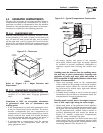
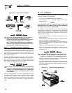
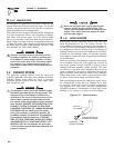
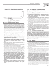
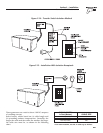
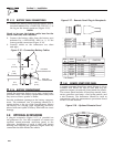
2.6.5 ISOLATING DIFFERENT POWER
SOURCES
Connections from the junction box must terminate in
a double-pole, double-throw transfer switch (Figure
2.14). An alternate method for isolating different
power sources is by using an isolating receptacle
(Figure 2.15). Whichever method is used, be certain
that both power sources are NOT connected at the
same time.
2.6.6 POWER SUPPLY CORD
The power supply cord must comply with all appli-
cable codes, standards and regulations. It must be
large enough to handle the full amperage to which it
will be subjected.
2.6.7 GROUND FAULT CIRCUIT
INTERRUPTERS
The National Electrical Code (NFPA 70, 551-7)
requires that ground fault circuit interrupters (GFCIs)
be installed on all external and some internal electri-
cal receptacles. Contact the dealer for recommenda-
tions.
2.7 BATTERY INSTALLATION
2.7.1 RECOMMENDED BATTERY
Install a battery that meets the following
requirements:
• The battery must be a 12-volt, automotive type
storage battery.
• For prevailing ambient temperatures above 32°
F (0° C), use a battery rated 70 amp-hours and
capable of delivering 400 cold-cranking amperes.
• For prevailing ambient temperatures below 32°
F (0° C), use a battery rated 95 amp-hours and
capable of delivering 400 cold-cranking amperes.
NOTE:
If the battery is to be used to power other vehicle
accessories, as well as start the generator, a bat-
tery with a larger capacity may be needed.
2.7.2 BATTERY CABLES
Using battery cables that are too long or too small in
diameter may cause a drop in voltage, which causes
starting problems. For the best cold weather starting,
the voltage drop between battery terminals and the
generator connection point should not exceed 0.12
volts per 100 amperes of cranking current.
Section 2 – Installation
Recreational Vehicle Generator