


27
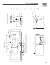
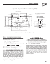
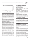
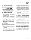
Figure 2.12 — Spark Arrestor Installation
40
[
1.58"
]
5.5
[
7/32"
]
DRIL
L
B
O
TT
O
M
S
IDE
O
NL
Y
27.4
[
1.08"
]
I.D
.
2.5.2 EXHAUST SYSTEM SAFETY
• Maintain a clearance of at least 3 inches (76 mm)
between exhaust system parts and any combus-
tible material (such as wood, felt, cotton, organic
fibers or other like material). If the 3-inch (76 mm)
clearance cannot be maintained, locate, insulate or
shield the exhaust part(s) so that the temperature
of any combustible material is not raised more
than 117° F (65° C) above the ambient air tempera-
ture.
• Extend the exhaust system at least 1 inch (25 mm)
past the outer edge of the vehicle. Do not terminate
the exhaust system under the vehicle.
• Terminate the exhaust tailpipe such that exhaust
gases will not be drawn back into the generator
compartment and recirculated.
• If there is any possibility of the tailpipe or muffler
being damaged, protect these damage-prone areas
by means of a protective device (such as a skid
bar).
• Install the generator exhaust system according to
safe automotive practices.
• Use enough exhaust system hangers to prevent any
part of the system from being dislocated.
• Use exhaust system parts recommended by the
manufacturer. Using unapproved exhaust mufflers
and exhaust system parts is the responsibility of
the person(s) installing such unauthorized parts.
• Do not terminate the exhaust system under any
opening, window or vent that can be opened or is
not permanently sealed from the vehicle interior.
• Exhaust piping must be large enough to prevent
excessive back pressure on the generator engine.
• Never tee the generator engine exhaust pipe into
the vehicle engine exhaust piping. This causes
excessive back pressure on the generator engine.
Also, water from one engine can damage the other
engine.
• Plan exhaust system installation carefully. Comply
with all applicable codes, standards and regula-
tions.
2.6 ELECTRICAL CONNECTIONS
Be sure to read Section 1.6.
The following general rules apply to electrical connec-
tions in a recreational vehicle:
• Qualified electricians who are familiar with appli-
cable codes, standards and regulations should
install electrical wiring.
• The wiring should comply with codes, standards
and regulations. The National Electrical Code
(NFPA 70), and state and local codes apply.
• Switches and circuit breakers should be of a type
approved for use in recreational vehicles and must
be mounted and installed to prevent damage from
road shock.
• Wiring must be of adequate size, have approved
insulative qualities and be properly supported.
• Conduit and wire openings into the generator com-
partment (if used) must be vapor-sealed to prevent
entry of flammable, explosive or poisonous gases
into the vehicle.
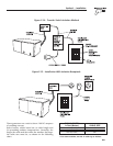
2.6.1 ELECTRICAL JUNCTION BOX
Install an approved, square electrical junction box
with a blank cover on the interior or exterior wall of
the area planed for installation of the generator (NOT
on the generator). Route the generator's AC output
leads into this junction box through approved flex-
ible conduit. This is the point of first termination for
generator AC output leads.
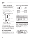
2.6.2 WIRING
• Wiring should be of stranded copper to reduce the
chance that vibration may cause breakage.
• Wire gauge size should be large enough to handle at
least 115 percent of the installed generator's rated
maximum current.
• Neutral conductors must be the same size as other
leg wires.
• Route power supply conductors from generator AC
output leads (white), (black) and the green ground
wire through approved flexible conduit to the elec-
trical junction box on the compartment wall.
If flexible metal conduit is used between the gen-
erator and the compartment junction box, the con-
duit end that terminates the compartment junction
box must be vapor-sealed. Flexible metal conduit
is NOT vapor tight along its entire length.
• From the junction box, route power supply wires
through approved conduit to either (a) double-pole,
double-throw transfer switch, or (b) approved iso-
lation receptacle. Connecting to a transfer switch
or isolation receptacle must prevent vehicle electri-
cal circuits from being connected to two different
power supplies at the same time (such as genera-
tor and dockside power).
Section 2 – Installation
Recreational Vehicle Generator