


23
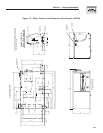
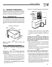
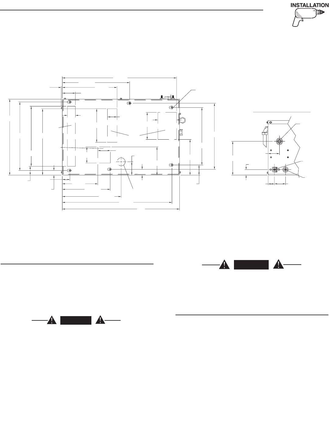
2.2.5 COMPARTMENT FLOOR CUTOUTS
Provide openings in the generator compartment for
the following items (Figure 2.7):
• Engine exhaust and cooling air outlets
• Generator cooling air inlet
• Four holes for passage of generator mounting
bolts. See Section 2.1.4.
DANGER
Fuel lines and exhaust piping must not pen-
etrate into the vehicle living area.
2.3 COOLING AND VENTILATING AIR
It is absolutely essential that an adequate flow of
air for cooling, ventilating and engine combustion
be supplied to the generator set. Without sufficient
airflow, the engine/generator quickly overheats. Such
overheating can cause serious operating difficulties
and also may cause fire and personal injury. The
installer must make sure that sufficient air is avail-
able to the generator for cooling, ventilating and
combustion. The installer also must provide for a
path for exhausting the cooling air to the exterior of a
compartment, if so equipped.
DANGER
Never use discharged cooling air for heating or
permit such air to enter the vehicle interior. This
air contains deadly carbon monoxide gas and
other poisonous, flammable or explosive gases.
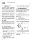
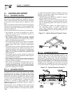
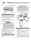
2.3.1 GENERATOR AIRFLOW
Engine operation drives cooling fans for the two-stage
cooling air system. A pressure fan draws cooling air
into the bottom right side of the generator (Figure
2.8). This airflow cools the engine/generator and elec-
tronic components. The second part of the cooling
system, a suction fan, draws air that is heated from
a hot engine into a collector compartment at the left
side of the unit. This heated air (although cooler than
exhaust muffler) is then deflected out the bottom
toward the ground.
Section 2 – Installation
Recreational Vehicle Generator
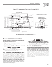
Figure 2.7 – Compartment Floor Cutout (Drawing 0F4610)
3
42.
2
[13 1/2"]
77
8
.
9
[
30 11/16"
]
REF.
FR
O
NT D
OO
R A
CC
E
SS
F
OR
ALL RE
Q
UIRED MAINTENANC
E
REM
O
TE PANE
L
CO
NNE
C
T
OR
500
.
2
[
19 11/16"
]
REF.
A
C
OU
TP
UT
HARNE
SS
H
O
T AI
R
EXHA
UST
TAIL PIPE
EXIT
O
IL DRAI
N
AIR
INTAKE
4
8
.
1
[
1 7/8"
]
222.7
[
8 3/4"
]
300
.
7
[
11 13/16"
]
369
.
7
[
14 9/16"
]
688
.
3
[
27 1/8"
]
2
9
[
1 1/8"
]
55
.
5
[
2 3/16"
]
3
7
6
.
5
[14 13/16"]
5/
1
6
"-1
8
WELDN
U
T
S
(
6 PLACES
)
8
2.
5
[
3 1/4"
]
3
4
3
.
4
[
13 1/2"
]
42
3
.
2
[
16 11/16"
]
717.7
[
28 1/4"
]
50
.
8
[
2"
]
11
8
[
4 5/8"
]
22
3
.
5
[8 13/16"]
60
[
2 3/8"
]
21
0
[8 1/4"]
17
6
.
6
[6 15/16"]
83
.
5
[
3 5/16"
]
42
9
.
5
[16 15/16"]
414.
5
[16 5/16"]
360
.
5
[14 3/16"]
63
.
5
[
2 1/2"
]
41
6
[16 3/8"]
17
0
[6 11/16"]
7
9
[
3 1/8"
]
1
01
[4"]
TYP.
6
.
7
[
1/4"
]
7
36
.
4
[
29"
]
47
6
.
4
[18 3/4"]
36
.
5
[1 7/16"]
[1 7/16
[1 7/16
39
.
6
[
1 9/16"
]
69
.
6
[
2 3/4"
]
3
4.
3
[
1 3/8"
]
71.2
[
2 13/16"
]
211.
3
[8 5/16"]
NE
G
. BAT
.
CO
NNE
C
TI
ON
P
OS
. BAT
.
CO
NNE
C
TI
ON
LP F
U
EL INLE
T
VIEW FR
O
M T
OP
N
O
TE: ALL AIR INTAKE
S
AND EXHA
US
T
OU
TLET
S
M
US
T B
E
KEPT
C
LEAR
O
F ANY
O
B
S
TR
UC
TI
O
N
S
. ALL
O
PEN ARE
A
IS RE
Q
UIRED FOR COOLING
.
CO
NNE
C
TI
O
N
S
IN
BA
C
K
O
F
G
ENERAT
OR
All measurements are in millimeters, 25.4 mm = 1”.