


24
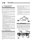
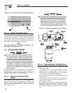
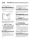
Figure 2.8 – Airflow Through Engine/Generator
2.3.2 TESTING THE INSTALLATION
The manufacturer recommends testing the installa-
tion to be sure adequate cooling airflow is available to
the unit before placing the unit into service. If the unit
shows signs of overheating, enlarge the air openings.
Never place a unit into service until absolutely certain
that cooling and ventilation is adequate.
NOTE:
Test the installation, especially if bringing in air
from below the generator set.
2.4 LP GAS FUEL SYSTEM
DANGER
LP gas is highly EXPLOSIVE. The gas is heavier
than air and tends to settle in low areas. Even
the slightest spark can ignite it and cause and
explosion. Only competent, qualified people
should be allowed to install, test, adjust or ser-
vice an LP gas fuel system. Install the optional
fuel system in compliance with applicable codes,
standards and regulations. After the installa-
tion, do not do anything that might render the
system in noncompliance with applicable codes
and standards.
The LP powered range of generators are fitted with a
nonadjustable, factory set system. These systems are
tamper-proof to meet 1997 California Air Resources
Board requirements for engine emission.
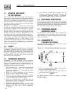
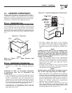
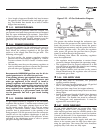
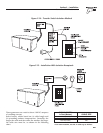
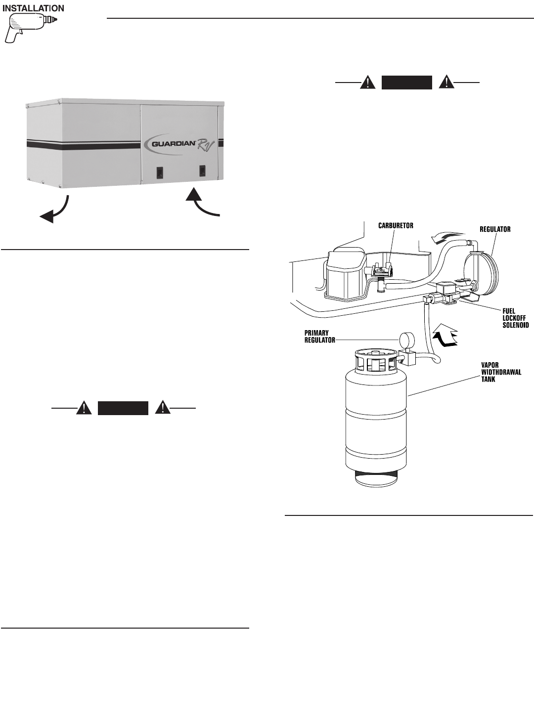
2.4.1 PARTS NOT INCLUDED IN FUEL
SYSTEM
The propane fuel system does NOT include such
items as (a) gas tank, (b) gas piping, (c) fittings, (d)
valves, and (e) primary regulator, used to store the
gaseous fuel and deliver it to the gaseous fuel sole-
noid (Figure 2.9).
DANGER
Use only approved components in the fuel sup-
ply system. All components must be properly
installed in accordance with applicable codes.
Improper installation or use of unauthorized
components may result in fire or an explosion.
Follow approved methods to test the system
for leaks. No leakage is permitted. Do not allow
fuel vapors to enter the vehicle interior.
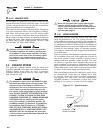
Figure 2.9 – Typical Propane Gas Fuel System
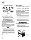
2.4.2 SOME IMPORTANT CONSIDERATIONS
When installing an LP gas system, consider seriously
the following items:
• All fittings, lines, hoses and clamps must be
tight and free of leaks. Apply a pipe sealant to
threads when assembling threaded connections.
This reduces the possibility of leakage.
• Test the entire fuel system for leaks using approved
test methods.
• Optimum gas pressure at the inlet to the gaseous
fuel solenoid valve and secondary regulator is 11
inches water column.
• The installer’s fuel supply connection point is at
the gaseous fuel solenoid valve. This is a 3/4-inch
(female) connection. Provide a suitable 3/4-inch
NPT (male) connector to attach to the fuel supply
line.
Section 2 – Installation
Recreational Vehicle Generator