


25
• Use a length of approved flexible fuel hose between
the gaseous fuel solenoid valve and rigid gas pip-
ing. The flexible line should be at least 6 inches
longer than necessary.
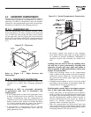
2.4.3 VAPOR WITHDRAWAL
LP gas is stored in pressure tanks as a liquid. The
gas systems used with these generators were designed
only for vapor withdrawal type systems. Vapor with-
drawal systems use the gas vapors that form above
the liquid fuel in the tank. Do NOT attempt to use the
generator with any liquid withdrawal type system.
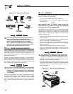
2.4.4 PRIMARY REGULATOR
Gas pressure delivered to the solenoid valve must be
properly regulated by means of a primary gas regu-
lator. Mount the primary regulator at the gas tank
outlet or in the supply line from the gas tank. The
following rules apply:
• For best results, the primary regulator supplies
gaseous fuel to the secondary regulator at 11 inch-
es water column. Do NOT exceed 14 inches water
column.
• The installer must be sure the primary regulator is
rated at sufficient gas flow to operate the generator
plus all other gas appliances in the circuit.
NOTE:
Recommended MINIMUM gas flow rate for all air-
cooled generators is 40 cubic feet per hour.
If an existing primary gas regulator does not have
a sufficient flow capacity for the generator and
other gas appliances in the circuit, (a) install a
primary regulator with adequate flow rate, or (b)
install a separate regulator only and rated at least
40 cubic feet per hour. The inlet side of any pri-
mary regulator that supplies the generator must
connect directly to a gas pressure tank. Do NOT
tee the generator line into a gas circuit feeding
other areas.
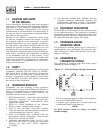
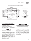
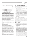
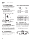
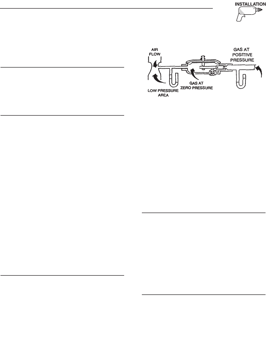
2.4.5 GASEOUS CARBURETION
LP gas vapors should be supplied to the secondary
regulator inlet at about 11 inches water column (posi-
tive pressure). The engine pistons draw air in dur-
ing the intake stroke (Figure 2.10). This air passes
through a carburetor venturi, which creates a low
pressure that is proportional to the quantity of air
being pumped. The low pressure from the carburetor
venturi acts on the regulator diaphragm to pull the
diaphragm toward the source of low pressure. A lever
attached to the diaphragm opens a valve to permit
gas glow through the carburetor.
Figure 2.10 – LP Gas Carburetion Diagram
The greater the airflow through the carburetor ven-
turi, the lower the pressure at the venturi throat. The
lower the pressure at the venturi throat, the greater
the diaphragm movement, and the greater the move-
ment of the regulator valve. The more the regulator
valve opens, the greater the gas flow that is propor-
tional to airflow through the generator.
The following facts about the secondary regulator
must be emphasized:
• The regulator must be sensitive to venturi throat
pressure changes throughout the operating range.
• The regulator must be properly adjusted so it will
stop the flow of gas when the engine is not running
(no air flow through the carburetor).
• The slightest airflow (and vacuum in the venturi
throat) should move the regulator valve off its seat
and permit gas to flow.
2.4.6 FUEL SUPPLY LINES
• LP gas lines must be accessible, but protected
against possible damage.
• Do NOT connect electrical wiring to any LP gas fuel
line or run wiring alongside the lines.
• Route gas lines away from hot engine exhausts.
• Retain gas lines with metal clamps that do not have
sharp edges.
• Install an approved length of flexible hose between
the gaseous fuel solenoid valve and rigid fuel
supply lines. The flexible line must be nonmetal-
lic, nonorganic and nonconductive. It must be
approved for use with LP gas.
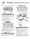
2.4.7 EXCESS FLOW VALVE
LP gas tanks should have an excess flow valve,
according to NFPA 501C, Paragraph 3-4.4. This
valve and the gas lines must be carefully sized so the
valve will close when a fuel line is severed or broken.
Consult the Natural-LP Gas Association for informa-
tion and limitations of excess flow valves.
Manual shutoff valves on the supply tank and else-
where in the system must be fully open when oper-
ating the generator. The excess flow valve functions
properly only if all valves are fully open.
Section 2 – Installation
Recreational Vehicle Generator