


5
1 Fan
Wheel
Dia.
1 Fan
Wheel
Dia.
R
o
t
a
t
i
o
n
R
o
t
a
t
i
o
n
R
o
t
a
t
i
o
n
R
o
t
a
t
i
o
n
Length of Straight Duct
GOOD
POOR
GOODPOOR
GOOD
POOR
Tu rning
Vanes
Tu rning
Vanes
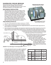
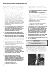
SYSTEM EFFECT FACTOR CURVES
FPM X 100
OUTLET VELOCITY
0 5 10 15 20 25 30 35 40 45
1.2
1.0
0.8
0.6
0.4
0.2
0.0
STATIC PRESSURE LOSS
CURVE 1
CURVE 2
CURVE 3
CURVE 4
1 Fan
Wheel
Dia.
1 Fan
Wheel
Dia.
R
o
t
a
t
i
o
n
R
o
t
a
t
i
o
n
R
o
t
a
t
i
o
n
R
o
t
a
t
i
o
n
Length of Straight Duct
GOOD
POOR
GOODPOOR
GOOD
POOR
Tu rning
Vanes
Tu rning
Vanes
SYSTEM EFFECT FACTOR CURVES
FPM X 100
OUTLET VELOCITY
0 5 10 15 20 25 30 35 40 45
1.2
1.0
0.8
0.6
0.4
0.2
0.0
STATIC PRESSURE LOSS
CURVE 1
CURVE 2
CURVE 3
CURVE 4
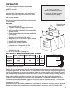
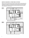
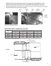
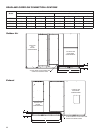
DUCTWORK CONNECTIONS
Examples of good and poor fan-to-duct connections are shown below. Airflow out of the fan should be directed
straight or curve the same direction as the fan wheel rotates. Poor duct installation will result in low airflow and
other system effects.
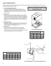
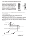
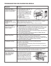
Rail Layout
• RailsdesignedtohandletheweightoftheHREshouldbe
positioned as shown on the diagram (rails by others).
• Makesurethatrailpositioningdoesnotinterferewiththesupply
air discharge opening or the exhaust air intake opening on the
HRE unit. Avoid area dimensioned “B” below
• Railsshouldrunthewidthoftheunitandextendbeyondtheunit
a minimum of 12 inches on each side.
• Setunitonrails.
AB
SUPPLY/EXHAUST
OPENING
OUTDOOR
AIR
INTAKE
HOOD
AB
SUPPLY/EXHAUST
OPENING
OUTDOOR
AIR
INTAKE
HOOD
Isometric view of HRE on rails
Side view of HRE on rails
Dimensions shown are in inches.
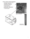
SUPPLY WEATHERHOOD
Supply weatherhood will be factory mounted.
EXHAUST WEATHERHOOD
The exhaust weatherhood is shipped separately as a kit with its own
instructions.
DAMPERS
Backdraft dampers are always included as an integral part of the
exhaust hood assemblies. Motorized outdoor air and exhaust air
dampers are optional and are factory mounted (and wired) at the
inlet.
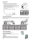
RAIL MOUNTING
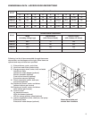
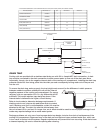
Recommended Discharge Duct Size and Length
HRE Model HRE Blower Size Duct Size Straight Duct Length
HRE-20 10 14 x 14 40
HRE-45 12 20 x 20 48
HRE-55 15 28 x 28 60
HRE-90 18 32 x 32 72
Model
Rail Mounting
A B
HRE-20 5.1 25.0
HRE-45 7.1 25.1
HRE-55 5.7 35.0
HRE-90 6.6 36.1
All dimensions shown are in inches.