


10
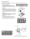
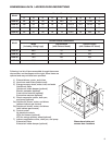
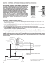
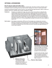
1. After the energy recovery unit is set in place, run the
overflow and drain lines to the exterior fittings on the
evaporative cooler (drain & overflow connections at
unit are 1-inch male pipe thread). The supply line can
be attached at the downstream side of the evaporative
cooler. A manual shut off valve should be mounted in
the supply line near the unit for servicing purposes.
Also, a trap should be installed in the drain line to
prevent air/sewer gas from being drawn into the unit
(refer to Drain and Overflow Connection Locations and
Drain Trap sections). Run bleed line into overflow.
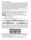
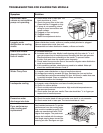
EVAP MODULE START-UP
1. The cooler will be prewired by the factory. (pumps are 115VAC).
2. Check to make sure that the pump filter is around the pump inlet.
3. Turn the water on and allow the sump to fill. Adjust the float valve to shut-off the water supply when the
sump is filled to a 1-inch height.
4. Open the bleed-off valve completely and saturate the media without any airflow through the unit. A jumper
wire is required on the terminal strip to provide power to the evaporative cooler pump (see the wiring
diagram for the proper location). This saturation process will break-in the media and minimize the odors
associated with the media. The media’s break-in period should
be no less than 20 minutes. When the process is complete,
remove the jumper wires in the control center.
Note:Evaporativemediamayfoamforashortperiod
following the initial start-up. Leave the bleed-off
valve fully open until the foaming stops.
5. After the media break-in period, the
water flow rate over the media needs to be
checked. The pumps should provide enough
water to saturate the media in 1-3
minutes. If adequate flow rate is
not achieved, adjust via water
flow adjustment device found on
water supply line running to evap
header.
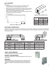
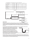
6. The water bleed-off rate will now need to be adjusted.
This measurement is 3 to 6 percent of the media flow
rate. The recommended flow rate is 1
1
/2 to 2 GPM
per square foot of media pad top area (see table at
right). Actual water to the unit will be based on the
evaporation rate. A water flow adjustment device is
supplied and installed by Greenheck for ease of water
flow adjustments. After the unit has been installed and
running for two weeks the unit should be checked for
mineral deposits. If there are deposits, the bleed-off
rate needs to be increased. Some areas of the country
have water with greater amounts of dissolved minerals
requiring a higher bleed-off rate.
Mount the heat recovery unit level to ensure proper
operation and water drainage. Piping should be of
adequate size to provide sufficient supply of water to meet
the maximum demand of the evaporative coolers.
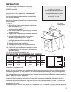
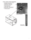
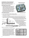
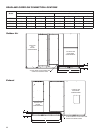
EVAP MODULE INSTALLATION
EVAPORATIVE COOLING MODULES
Indirect Evaporative Cooler
(Exhaust/Scavenger Airstream)
Direct Evaporative Cooler
(Outdoor/Supply Airstream)
Roof Curb
Roof Line
Drain
Line
Trap
Overflow
Drain Line
Manual
Shutoff
Valve
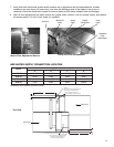
Evaporative
Cooling
Media
Manual Shutoff Valve
Supply Line
Sump
Side of HRE Unit
Standard Trap and Supply Line Configuration
Media Size
(w x h x d) (in.)
Media Pad
Top Area
HRE-20
Supply
Exhaust
18 x 36 x 12
18 x 36 x 12
1.5 ft
2
1.5 ft
2
HRE-45
Supply
Exhaust
30 x 48 x 12
24 x 48 x 12
2.5 ft
2
2.0 ft
2
HRE-55
Supply
Exhaust
36 x 56 x 12
30 x 56 x 12
3.0 ft
2
2.5 ft
2
HRE-90
Supply
Exhaust
48 x 69.5 x 12
40 x 69.5 x 12
4.0 ft
2
3.3 ft
2