


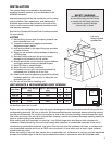
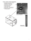

11
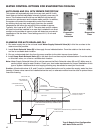
7. Verify that both airflow and system static pressure are in agreement with the specifications. If these
conditions are met, check for water carry over from the discharge side of the media. If carry over is
observed, check the distribution header for holes or tears and the water standoff tube for blockage.
8. After all final adjustments are made, remove the jumper wires, connect “call for cooling” signal, and replace
all access panels. The unit is now ready for operation.
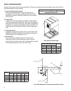
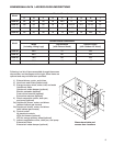
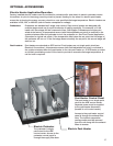
Bleed-Off
Valve
Overflow
Pump
Filter
Threaded
Float
Adjustment
Supply
Connection
Float
Valve
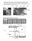
Pump and Float Components
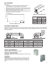
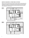
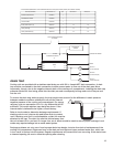
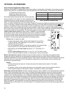
HRE WATER SUPPLY CONNECTION LOCATION
B
A
Ø
0.875
Run 1/4 inch line up through 7/8 inch
hole here and bring around end
of sump to supply connection.
D
C
Ø
0.875
Run 1/4 inch line up through 7/8 inch
hole here and bring around end
of sump to supply connection.
OA INLET
EA INLET
1/4 inch Water Supply Connection
1/4 inch Water Supply Connection
Model
Water Supply Connection Locations
A B C D
HRE-20 37.375 4.625 4.625 39.25
HRE-45 38.75 4.625 4.625 43.00
HRE-55 43.50 4.625 4.625 46.125
HRE-90 43.50 4.625 4.625 52.625
Dimensions from outside of unit (in inches)
Top View
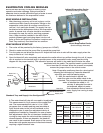
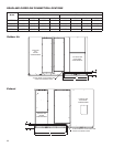
Water Flow Adjustment Device