


3
INSTALLATION
The system design and installation should follow
accepted industry practice, such as described in the
ASHRAE Handbook.
Adequate space should be left around the unit for piping
coils and drains, filter replacement, and maintenance.
Sufficient space should be provided on the side of the
unit for routine service and component removal should
that become necessary.
See Service Clearances/Access Panel Locations section
for more details.
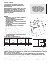
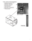
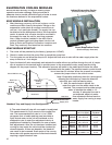
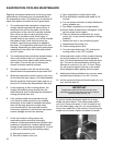
LIFTING
1) Before lifting, be sure that all shipping material has
been removed from unit.
2) To assist in determining rigging requirements,
weights are shown below.
3) Unit must be lifted by the eight lifting lugs provided
on base structure.
4) Rigger to use suitable mating hardware to attach to
unit lifting lugs.
5) Spreader bar(s) must span the unit to prevent
damage to the cabinet by the lift cables.
6) Always test-lift the unit to check for proper balance
and rigging before hoisting to desired location.
7) Neverliftunitsbyweatherhoods.
8) Neverliftunitsinwindyconditions.
9) Preparation of curb and roof openings should be
completed prior to lifting unit to the roof.
10) Check to be sure that gasketing (supplied by others)
has been applied to the curb prior to lifting the unit
and setting on curb.
11) Do not use fork lifts for handling unit.
Lift using
lifting lugs and
spreader bar
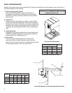
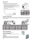
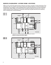
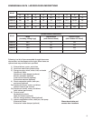
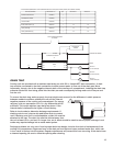
UNIT WEIGHTS & RECOMMENDED ROOF OPENING
SUPPLY
OUTLET
EXHAUST
INLET
U
V
0.50
0.50
Unit Size
Approx. Dry Weight
(lbs)
Approx. Wet Weight
(lbs)
U V
HRE-20 1660 1800 46 37
HRE-45 2580 2840 54 39
HRE-55 2950 3320 65 47
HRE-90 4750 5400 85 49
SAFETY WARNING
All factory provided lifting lugs must
be used when lifting the units. Failure
to comply with this safety precaution
could result in property damage,
serious injury, or death.
Unit weights assume indirect evap, direct evap, and IG furnace.
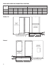
All dimensions shown are in inches.
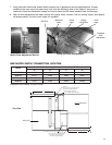
Position the unit roof opening such that the supply discharge and exhaust inlet of the unit will line up with the
corresponding ductwork. Be sure to allow for the recommended service clearances when positioning opening
(see Service Clearances). Do not face the outdoor air inlet of the unit into prevailing wind and keep the supply
inlet of the unit away from any other exhaust fans. Likewise, position the exhaust discharge opening away from
fresh air intakes of any other equipment.
When cutting only duct openings, cut opening 1 inch (25mm) larger than duct size to allow clearance for
installation. Area enclosed by roof curb must comply with clearance to combustible materials. If the roof is
constructed of combustible materials, area within the roof curb must be ventilated, left open, or covered with
non-combustible material which has an ÒRÓ value of at least 5. If area within curb is open, higher radiated
sound levels may result.
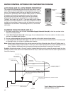
Where the supply or warm air duct passes thru a combustible roof, a clearance of one inch must be maintained
betweentheoutsideedgesoftheductandcombustiblematerialinaccordancewithNFPAStandard90A.