


13
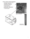
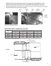
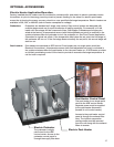
Coolingcoilsareprovidedwithastainlesssteeldrainpanwith3/4-in.femaleNPTdrainconnection.Adrain
trap must be connected to the drain connection to allow excess water to flow out of the drain pan. More
importantly, though, due to the negative internal static of the cooling coil compartment, installing the drain trap
prevents outdoor air from being pulled into the drain pan and consequently forcing water out of the pan and
into the unit.
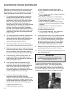
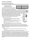
To ensure the drain trap works properly, the trap height must account for the difference in static pressure
between ambient conditions outside the unit and the internal
negative pressure of the cooling coil compartment. For energy
recovery units, an assumption of 3.0 in. wg. differential will be
sufficient. This would require a trap design as shown. If the
internal static is believed to be higher, consult factory.
Refer to local codes to determine drainage requirements. If
draining onto to roof, place a drip pad below drain to protect
roof. If draining onto roof is not acceptable, a drain line must be
attached to the trap. The drain line must be pitched away from
the unit at least 1/8-in. per foot. On longer runs, an air break should be used to ensure proper drainage. Local
codes may require drainage into a waste water system.
Drainage problems not only occur from improper drain trap design, but also from lack of maintenance of the
cooling coil compartment. Algae can form in the drain pan and trap and cause reduced water flow, which can
in turn result in backup into the system. Regular maintenance will prevent this from occurring. If the drains have
a cleanout opening, be sure to close the opening after cleaning.
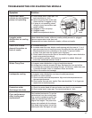
A1
B1
15
NC
JC
COM
TIMER
JC
18
A2
16
VC
VB
VA
JOHNSON CONTROLLER
24VAC COMSENSOR
24V AC POWER AND WIRING
BY OTHERS
SENSOR
OUTDOOR AIR
VALVE "A"
VALVE "B"
VALVE "C"
TIMER
OUTDOOR AIR SENSOR
T1
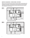
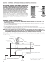
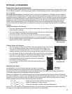
AUTO DRAIN AND FILL WITH FREEZE PROTECTION
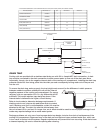
PART DESCRIPTIONS
VALVE, WATER SUPPLY (A)
VALVE, DRAIN (B)
VALVE, SUMP DRAIN (C)
24 HOUR TIMER
JOHNSON CONTROLLER
GREENHECK P/NQTY.
07458032 1
07381940 1
05461262 1
05461263 1
05461264 1
OUTDOOR AIR SENSOR
07458298 1
1/2 PIPE SIZE (NC)
1/4 PIPE SIZE (NO)
3/4 PIPE SIZE (NO)
-
25
25
25
-
-
HOLDING VA INRUSH VA
-
70
50
70
-
-
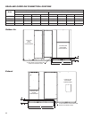
SUMP
EVAPORATIVE
COOLING MEDIA
ROOF CURB
ROOF LINE
TRAP
DRAIN LINE
SUPPLY LINE
WATER SUPPLY SOLENOID VALVE (A)–NORMALLY CLOSED
1/2 INCH PIPE SIZE
DRAIN SOLENOID VALVE (B)–NORMALLY OPEN
1/4 INCH PIPE SIZE
SUMP DRAIN SOLENOID VALVE (C)–NORMALLY OPEN
3/4 INCH PIPE SIZE
SIDE OF HRE UNIT
SUMP DRAIN PIPE
(TO EACH EVAP)
SUMP OVERFLOW PIPE
(TO EACH EVAP)
THE SYSTEM WILL AUTOMATICALLY DRAIN THE SUMP TANK AND FILL IT WITH FRESH WATER AT THE FIELD ADJUSTABLE INTERVALS, TYPICAL SETTINGS ARE t1 = 24HRS
t2 = 10 MIN. WITH THE DIP SWITCH IN THE DOWN POSITION. THIS FLUSHES MINERAL BUILD-UP AND DEBRIS FROM THE TANK TO PROMOTE LOW MAINTENANCE AND
INCREASE MEDIA PAD LIFE. IN ADDITION, THE SYSTEM WILL PROTECT THE EVAPORATIVE COOLER FROM FREEZING BY DRAINING THE SUMP TANK AND SUPPLY LINE
WHEN THE OUTSIDE TEMPERATURES FALL BELOW THE SET POINT OF THE OUTDOOR AIR SENSOR. TYPICALLY, THIS IS SET AT 45° TO 50° F. THE AUTO DRAIN AND FILL
OUTDOOR AIR SENSOR SHOULD BE INSTALLED IN AN AREA THAT IS SHADED FROM DIRECT SUNLIGHT SO THE SENSOR PROBE WILL DETECT AN ACCURATE AIR
TEMPERATURE.
THE FOLLOWING COMPONENTS SHIP FROM GREENHECK WITH HRE (INSTALLATION, WIRING, AND POWER BY OTHERS)
WATER LINE CONNECTION
AT FLOAT IS 1/4 INCH
4 in.
2 in.
DRAIN TRAP