


GB - 21
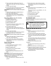
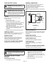
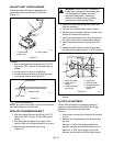
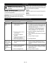
ADJUST SHIFT LEVER LINKAGE
The transmission shift lever is attached to the
transmission shift arm with two 5/16-18 bolts
(Figure 11).
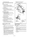
To adjust:
1. Stop the engine. Remove ignition key. Put PTO
lever in the "OFF" position. Put the shift lever in
neutral.
2. Loosen two 5/16-18 bolts in shift lever.
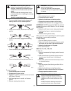
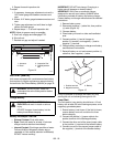
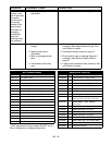
3. Center shift lever vertically in forward slot, just
touching the reverse stop (Figure 12).
4. Tighten bolts securely.
NOTE: You should not be able to shift into reverse with-
out pushing down on the shift lever.
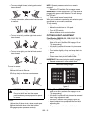
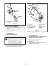
REPLACE TRANSMISSION BELT
1. Stop the engine. Remove ignition key. Put PTO
lever in the "OFF" position. Put the shift lever in
neutral.
2. Remove mower drive belt from mower clutch
sheave. Refer to Belt Replacement for your deck.
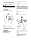
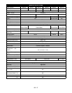
3. Remove transmission belt idler spring
(Figure 13).
4. Loosen one and remove one front engine bolt.
Save the hardware.
5. Turn the clutch bracket away from the clutch.
6. Remove old transmission belt from mower clutch
sheave and transmission sheave.
7. Install new transmission belt in the top groove of
the clutch hub and on the transmission sheave.
8. Install transmission belt idler spring to tension
belt.
9. Reposition clutch bracket, replace engine bolt,
and torque both engine bolts to 17 lbf-ft (23 N•m).
10. Reinstall mower drive belt on mower clutch
sheave.
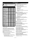
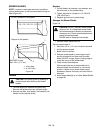
CLUTCH ADJUSTMENT
If clutch fails to engage or disengage properly or
begins to make abnormal noise, check the air gap
adjustment at the three inspection slots.
To check:
1. Stop engine, remove key and wait for all hot parts
to cool.
2. Measure the air gap between the armature and
the rotor.
Minimum: A .005" feeler gauge should slide
between armature and rotor with slight contact.
Maximum: A .023" feeler gauge should slide
between armature and rotor with slight contact.
OG1230
1. Transmission
2. Shift Lever
3. 5/16-18 Bolts
1
3
2
Figure 11
OG1240
Reverse Stop
Center in Slot
Shift Lever
Figure 12
WARNING: AVOID INJURY. An extension
spring, when extended, stores energy and
can be dangerous. Always use tools
specifically designed for installing or
removing an extension spring. Always
compress or extend springs slowly.
1
2
3
4
5
OG0792
Figure 13
1. Mower Drive Belt
2. Mower Clutch
Sheave
3. Transmission Belt
Idler Spring
4. Engine Bolt
5. Clutch Bracket
6. Transmission Belt
7. Transmission
Sheave
6
7