


GB - 20
REPLACE TRACTION BELTS
1. Turn off the engine, remove the key and allow unit
to cool.
2. Release the steering levers (988100, 101, 102,
103, 104, 110, 112).
3. Raise the rear of the unit so that the drive wheels
are off the ground.
4. Remove traction belt guard.
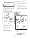
5. Remove clutch idler pulley spring (Figure 10).
6. Remove hair pin and clevis pin holding steering
control rod to wheel clutch arm weldment.
7. While slowly turning the drive wheel, work the
traction belt off the transmission shaft pulley and
drive wheel.
8. Install new traction belt.
9. Connect steering control rod to wheel clutch arm
weldment with clevis pin and hair pin.
10. Replace clutch idler pulley spring.
11. Replace traction belt guard.
12. Lower the unit.
13. Check steering lever adjustment. See Adjust
Steering Levers on page 19.
WARNING: AVOID INJURY. An extension
spring, when extended, stores energy and
can be dangerous. Always use tools
specifically designed for installing or
removing an extension spring. Always
compress or extend springs slowly.
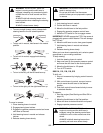
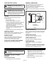
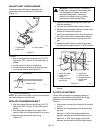
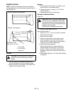
Wing Nut
Brake Rod
Brake Band
Figure 9
OG1350
Note: Some components removed
for clarity.
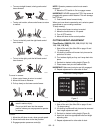
OG0751
1
2
3
4
5
6
8
9
7
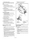
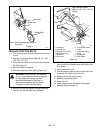
1. Handlebar
2. Steering Lever
3. Steering Control Rod
4. Wheel Clutch Arm
Weldment
5. Brake Rod
6. Transmission Shaft
Pulley
7. Clutch Idler Pulley
Spring
8. Traction Belt
9. Drive Wheel
Figure 10
Note: 988100 Shown.
988114, 115, 118, 119, 313
Similar.