


GB - 19
5. Adjust tracking if needed.
Try each of the following steps until the unit tracks
straight. It may not be necessary to perform all the
steps.
If unit turns to the right:
1. Reduce the air pressure in the left tire.
2. Increase the air pressure in the right tire.
3. Check for brake binding on right wheel and adjust
as needed.
If unit turns to the left:
1. Reduce the air pressure in the right tire.
2. Increase the air pressure in the left tire.
3. Check for brake binding on left wheel and adjust
as needed.
Check Reverse Tracking
1. Adjust forward tracking (See Check Forward
Tracking on page 18).
2. Move shift lever into Reverse and slowly pull up
on the lower control levers.
3. Note which direction, if any, the unit pulls.
4. Stop unit and engine.
5. Adjust tracking if needed.
If unit turns to the right:
1. Reduce the air pressure in the left tire.
2. Increase the air pressure in the right tire.
3. Check reverse tracking and adjust as needed.
If unit turns to the left:
1. Reduce the air pressure in the right tire.
2. Increase the air pressure in the left tire.
3. Check reverse tracking and adjust as needed.
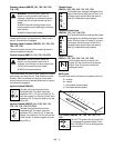
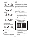
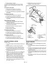
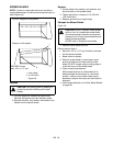
ADJUST STEERING LEVERS
For each lever:
1. Turn off the engine, remove the key and allow unit
to cool.
2. Release steering or control levers (Figure 8).
3. Shift transmission into neutral. Operate steering
or control lever several times. Do not move unit.
4. Remove hair pin and clevis pin from the clevis on
the steering control rod.
5. 988100, 101, 102, 103, 104, 110, 112: Adjust the
clevis on the steering control rod until the gap
between the ends of the steering lever and
handlebar grip is 2-1/2 to 3 in. (6.35-7.6 cm).
988114, 115, 118, 119, 313: Set pivot bar all the
way forward, and then adjust the clevis on the
steering control rod until the gap between the
ends of the control lever and pivot bar is 2-1/2 to
3 in. (6.35 - 7.6 cm).
6. Reinstall the clevis pin and hair pin.
7. Repeat for other steering lever.
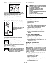
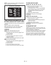
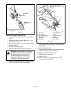
ADJUST BRAKES
NOTE: The traction belt must disengage as the brake
starts to engage.
1. Turn off the engine, remove the key and allow unit
to cool.
2. If brakes do not disengage fully when traction belt
is engaged, the brakes are too tight. Loosen the
wing nut (Figure 9).
3. If brakes do not engage fully when traction belt is
disengaged, the brakes are too loose. Tighten the
wing nut.
4. Start engine and test in low gear for proper brake
engagement.
Figure 8
1. Hair Pin
2. Clevis Pin
3. Clevis
4. Steering Lever
5. Steering Control Rod
6. Pivot Bar
7. Control Lever
8. Control Stop Lock
Lever
1
2
3
4
5
OG0752
2-1/2 - 3"
(6.35 - 7.6 cm)
2-1/2 - 3"
(6.35 - 7.6 cm)
7
6
8