OneWASH™ Power Washer 7
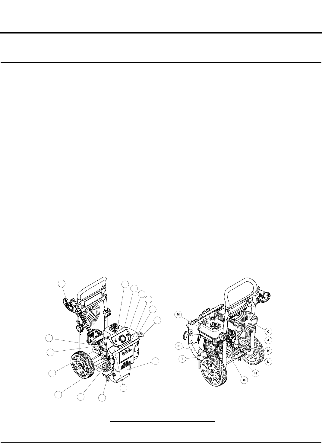
3.1 — KNOW YOUR POWER WASHER
Read this owner’s manual and safety rules before operat-
ing your high power washer. If you loan this device to
someone, ALWAYS loan these instructions AND the
owner’s manual to the individual as well. Compare the
illustrations with your high power washer to familiarize
yourself with the locations of various controls
(Figure 3-1). Save this manual for future reference.
Replacement owner’s manuals can be printed from the
Generac Web site.
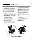
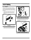
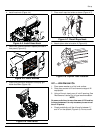
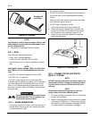
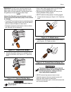
A-Spray Gun – Controls the application of water onto
the cleaning surface with trigger device. Includes a
trigger lock.
B -Lance with Quick Connect – Allows you to switch
between different nozzles.
C -High Pressure Hose – Connect one end to water
pump and the other to the spray gun.
D -Recoil Starter – Use for starting the engine.
E -Oil Fill – Check and add engine oil.
F-Air Filter – Protects engine by filtering dust and
debris out of the intake air.
G-Pump – Develops high pressure.
H -Thermal Relief Valve – Cycles water through the
pump when water reaches 125°F warm water will
discharge from pump onto ground. This prevents
internal pump damage.
I -Engine On/Off Switch – Turn this switch to “ON”
before using the recoil starter. Turn the switch to
“OFF” to stop the engine.
J -Unloader Valve – Controls the high pressure output.
K -High Pressure Outlet – Connection for high pres-
sure hose.
L -Water Inlet – Connection for Garden Hose.
M -Fuel Tank – Fill tank with regular unleaded fuel.
Always leave room for fuel expansion.
O -Choke – Prepares a cold engine for starting.
P-Power Dial – Provides optimal cleaning power for
each desired application.
Q -Nozzles – Chemical injection, Blast (0°), Wash (25°),
Detergent for various high pressure cleaning applica-
tions.
R -Chemical Tank – A drain-able tank used to hold
power washer safe detergents to be siphoned into
the low pressure stream.
S -Prepare/Start Instruction – Identifies proper proce-
dure to set up and start/stop power washer.
T -Drain Plug – Used to drain engine oil.
U -Serial Number Location
V -Chemical Tank Fill Cap
W -Chemical Tank Drain Cap
Figure 3-1. Features and Controls
I
U
O
Q
P
S
D
R
S
W
V
F
H
B
A
Section 3 General Information


