6
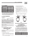
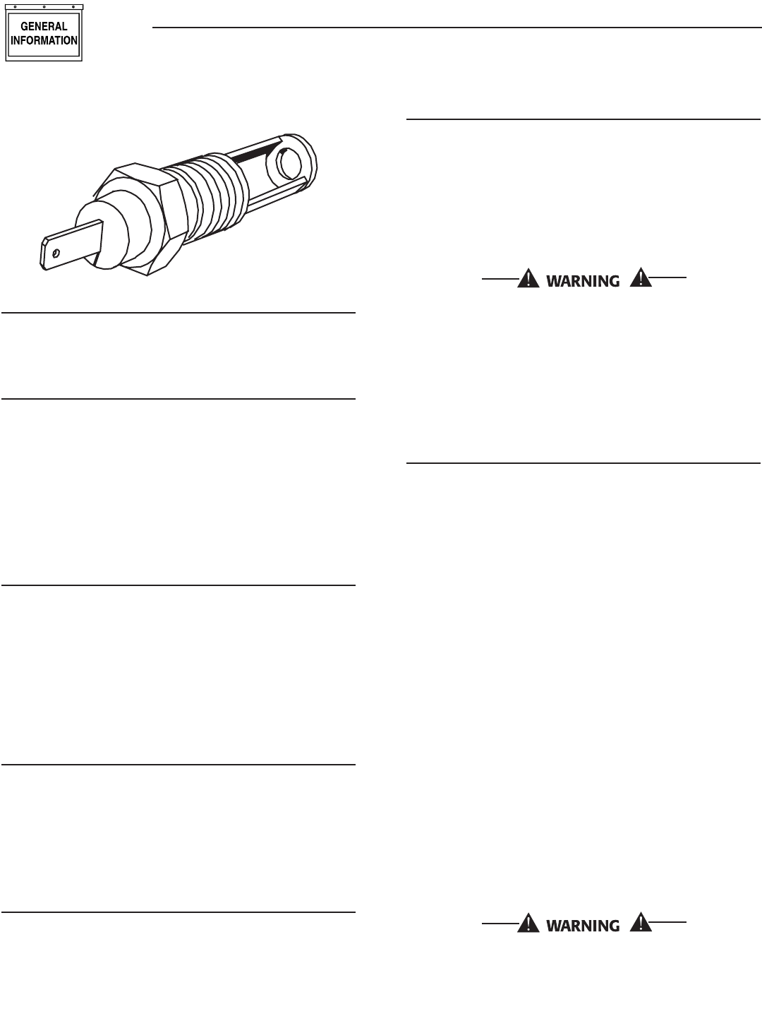
Figure 1.6 - Low Coolant Level Sensor
1.7.4 OVERSPEED SHUTDOWN
Should AC frequency exceed about 72 Hz, cir-
cuit board action will automatically shutdown the
engine.
1.7.5 OVERCRANK SHUTDOWN
The engine control board uses a cyclic cranking pro-
cess when attempting to start the engine. The first
crank cycle is a 15-second crank followed by a seven-
second rest. This is followed by five more crank
cycles each with a seven second crank followed by a
seven-second rest.
If the engine fails to start after all six attempts, the
start attempt is stopped and the overcrank LED turns
on.
1.7.6 LOW BATTERY
The engine control board continually monitors the
battery voltage and turns on the low battery LED if
the battery voltage falls below 12 VDC for one minute.
Low battery voltage is a non-latching alarm, which
will automatically clear if the battery voltage rises
above 12 VDC. If battery voltage goes below 6 VDC
during cranking, the low battery voltage alarm is
latched, cranking is terminated, and the low battery
LED stays on.
1.7.7 15A DC FUSE
This fuse is located inside the control panel. It pro-
tects the panel wiring and components from damag-
ing overload. The unit will not start or crank if the
fuse is blown. Replace the fuse with one of the same
size, type, and rating.
1.8 UNPACKING
1.8.1 UNPACKING PRECAUTIONS
Handle shipping cartons and crates with care. Use
care to avoid damage from dropping, bumping, colli-
sion, etc. Store and unpack cartons with the proper
side up, as noted on the shipping carton.
1.8.2 INSPECTION
Upon delivery, carefully inspect the generator for any
damage that may have occurred during shipment. If
loss or damage is noted at the time of delivery, have
the person(s) making delivery note all damage on the
freight bill or affix their signature under the consign-
or’s memo of loss or damage.
1.9 LIFTING THE GENERATOR
When lifting or hoisting equipment is used, be
careful not to touch overhead power lines. The
generators weight of more than 900 pounds
requires proper tools, equipment, and qualified
personnel to be used in all phases of handling
and unpacking.
1.10 SPECIFICATIONS
1.10.1 ENGINE
Make ...................................................................................... Ford
Displacement ............................................153 inches
3
(2.5 liters)
Cylinder Arrangement .....................................................4, in-line
Valve Arrangement ............................................... Overhead Cam
Firing Order .......................................................................1-3-4-2
Number of Main Bearings ...........................................................5
Compression Ratio ......................................................... 9.37 to 1
No. of Teeth on Crank ............................................................ 36-1
Ignition Timing (Waste Spark System)
at 1800 rpm (NG) ..........................................36 degrees BTDC
Ignition Timing (Waste Spark System)
at 1800 rpm (LP vapor) ............................... 28` degrees BTDC
Spark Plug Gap ............................................................0.044 inch
Recommended Spark Plugs
Motorcraft ................................................................. AWSF-52-C
Oil Pressure ....................................................................30-50 psi
Crankcase Oil Capacity ......................4.5 U.S. quarts (4.26 liters)
Recommended Engine Oil .......................................SAE 15W-40
Type of Cooling System ................. Pressurized, closed recovery
Cooling Fan ...............................................................Pusher Type
Cooling System Capacity ...................... 2 U.S. gallons (7.6 liters)
Recommended Coolant ............. Use a 50-50 mixture of ethylene
glycol base and deionized water.
Home standby control board assembly part num-
ber 0E9704 must be used on 1800 rpm genera-
tors.
Section 1 — General Information
Liquid-cooled 25 kW Generators


