


16
3.6 AUTOMATIC OPERATION
To set the system for fully automatic operation, pro-
ceed as follows:
• Check that load circuits are connected to the
utility power supply.
• Set the AUTO/OFF/MANUAL switch to its AUTO
position.
• Set the generator main circuit breaker to its ON or
CLOSED position.
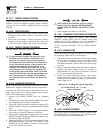
3.7 WEEKLY EXERCISE CYCLE
The engine control board will start and run the gen-
erator once every seven days for approximately 12
minutes. If utility should fail during this exercise
period, the engine control board will transfer the load
to the generator output and continue to run until util-
ity returns.
On the day, and at the time of day chosen for the
generator to exercise, set the weekly exercise cycle
as follows:
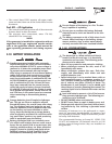
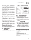
1. Place the AUTO/OFF/MANUAL switch in the
AUTO position (Figure 3.3).
2. Press and hold the “Set Exercise Time” switch for
five seconds, then release.
At this time all five red LEDs will flash for approxi-
mately 10 seconds, then the engine will start and run
for it’s 12 minute exercise period, then shut down.
The generator will now start and run each week at
the same time.
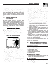
Figure 3.3 - “Set Exercise Time” Switch
ON
0
F2
6
2
9
THEN THE UNIT WILL START
,
RUN THROUGH THE EXERCISE CYCLE AND SHUTDOWN
.
MAN
U
A
L
S
E
T
EXER
C
I
SE
TIME
T
O
S
ET EXER
C
I
S
ER TIM
E
2
)
HOLD "SET EXERCISE TIME" SWITCH IN "ON" POSITION FOR THREE SECOND
S
AND RELEASE.
(
SEE OWNER'S MANUAL FOR COMPLETE DETAILS
)
THE EXER
C
I
S
ER I
S
N
O
W
S
ET. ALL FIVE RED LED'
S
WILL FLA
S
H F
O
R 1
0
S
E
CO
ND
S
1
)
PLACE AUTO/OFF/MANUAL SWITCH TO AUTO POSITION
.
A
U
T
O
O
F
F
O
F
F
(
SEE OWNER'S MANUAL FOR COMPLETE LED DETAILS
)
If DC power to the control board is lost, the weekly
exercise setting will be lost. This is indicated by all
five red LEDs continually flashing. In this state the
generator will still start and run in manual mode, or
automatically start and run if utility is lost while in
Auto mode, but it will not perform a weekly exercise
cycle.
If a failure occurs while running in this mode, the
five red LEDs will stop flashing, the individual fault
LED will turn on and the engine will shut down. Once
the AUTO/OFF/MANUAL switch has been switched to
OFF, the individual fault LED will turn OFF and the
five red LEDs will begin flashing to show exercise has
still not been set.
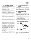
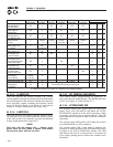
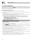
3.8 CONTROL BOARD DIP SWITCH
SETTINGS
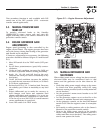
Located on the control board is an eight position DIP
switch (see Figure 3.2). The eight different switches,
are used to configure the control board for the spe-
cific engine and governor being used and are pre-set
at the factory.
If the DIP switch settings are not set correctly,
the generator may not start or operate correctly.
240 VAC can be present within the control panel.
If it is necessary to select an alternate switch posi-
tion, move the AUTO/OFF/MANUAL switch to the
OFF position. Remove the 15 amp fuse in the genera-
tor control panel. Move the DIP switch position that
needs to be changed to its new position. Wait five
seconds, then re-install the 15 amp fuse.
The ON position is marked on the switch and is
shown in Figure 3.2.
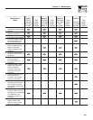
Switch Position 1 — Selects the generator alternator
output frequency and is factory pre-set for 60 Hz.
Switch Position 2 — Selects the type of transfer
switch and is factory pre-set for an automatic trans-
fer switch (ATS).
Switch Position 3 — Selects the type of governor
control used, and is factory pre-set for stepper motor
operation.
Switch Position 4 — Selects the type of fuel being
used and is factory pre-set for natural gas (NG).
Switch Position 5 — Selects the engine displacement
and is factory pre-set for a 2.5 liter (2.5L) engine.
Switch Position 6 — Selects the number of engine
cylinders and is factory pre-set for four cylinders.
Switch Position 7 — Selects the direction of rotation
of the governor stepper motor and is factory pre-set
for CCW rotation (rotation is observed looking at the
stepper shaft as it moves from closed throttle to open
throttle).
Section 3 - Operation
Liquid-cooled 25 kW Generators