


13
• After the engine starts and when the generator
AC output voltage and frequency have reached a
pre-set value, transfer switch circuits signal the
transfer switch main contacts to actuate to the
“Standby” power source side. Generator AC output
then powers load circuits.
• When the utility power source voltage is restored
above a pre-set level, transfer switch circuits signal
the switch main contacts to move back to their util-
ity power source side.
• Following re-transfer back to the utility power
source side, transfer switch circuit board action
signals the generator to stop. Engine then shuts
down.
GTS Mode Operation
When in GTS mode, the control board will respond as
follows based on the generator AUTO/OFF/MANUAL
switch position.
OFF — The generator will not start and run in this
position.
MANUAL — The control board will start and run
the generator whenever the switch is in the manual
position.
AUTO — The control board will monitor the two-wire
start circuit. When a two-wire start is issued, the con-
trol board will immediately start and run the genera-
tor. When the two-wire start is removed the control
board will immediately stop the generator.
NOTE:
If the generator is installed in conjunction with an
engineered GTS type transfer switch, refer to the
applicable transfer switch manual for exact oper-
ating parameters and timing sequences.
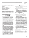
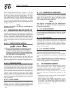
For proper battery charger operation, it will be nec-
essary to supply a fused 240VAC utility fed supply to
terminals N1 and N2 in the control panel.
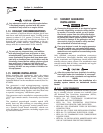
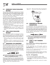
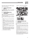
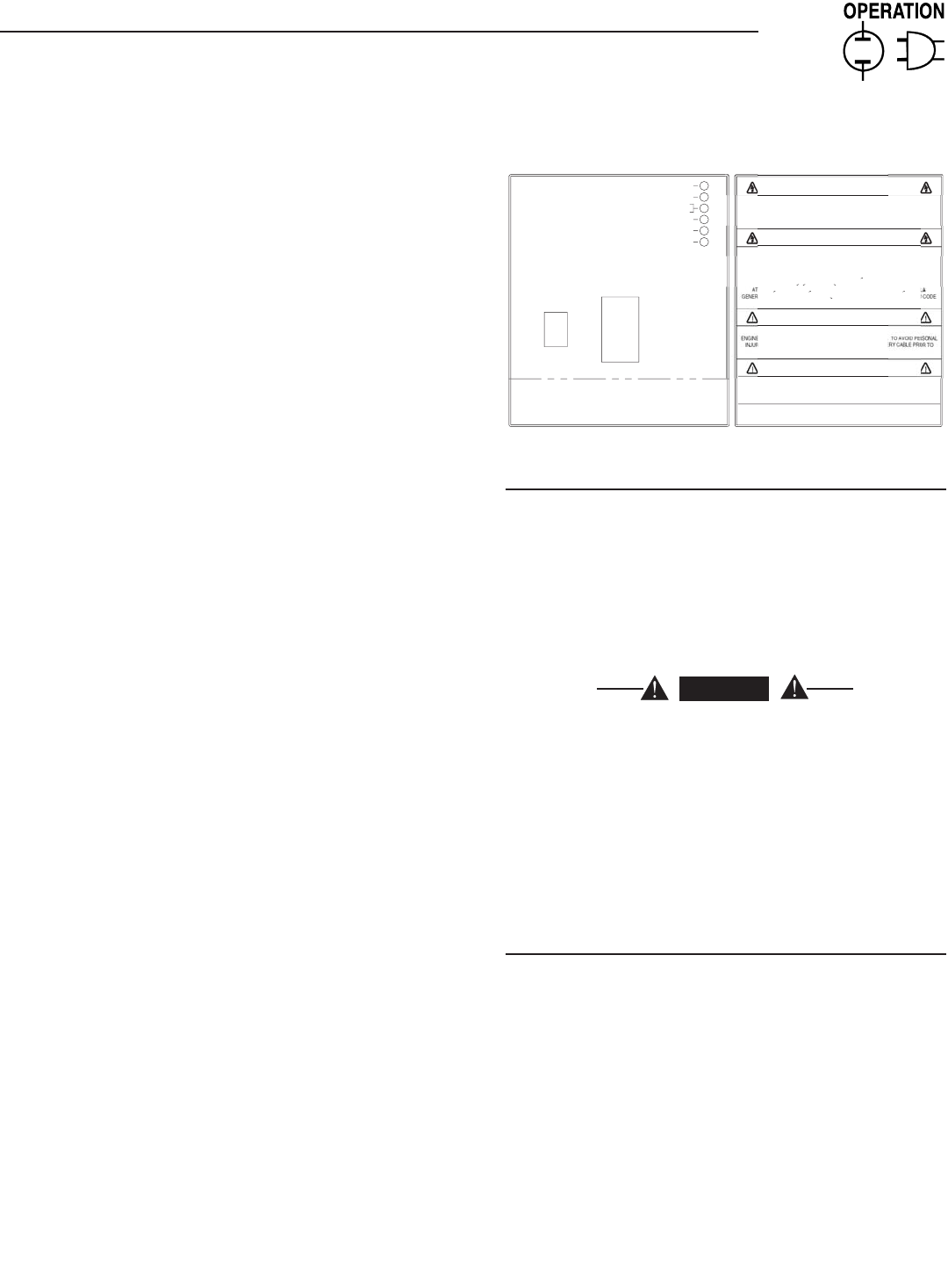
3.2 CONTROL CONSOLE
COMPONENTS
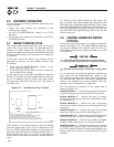
The components of a home standby generator control
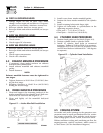
console (Figure 3.1) are as follows:
Figure 3.1 - Generator Control Console
C
A
U
TI
ON
RI
S
K
O
F ELE
C
TRI
C
AL
S
H
OC
K. D
O
N
O
T REM
O
VE
CO
VER. N
O
US
ER
S
ERVI
C
EABLE
PARTS INSIDE. REFER SERVICING TO
Q
UALIFIED SERVICE PERSONNEL
.
C
A
U
TI
ON
F
O
R
S
TAND-BY
S
ERVI
C
E
CO
NNE
C
T
OU
TP
U
T
O
F
G
ENERAT
O
R T
O
SU
ITABLY RATED
TRANSFER SWITCH IN ACCORDANCE WITH CANADIAN ELECTRICAL CODE
,
PART I
.
TENTION: POUR L'ALIMENTATION DE RESERVE, CONNECTER LA SORTIE DE
ATRICE A UN COMMUTATEUR DE CALIBRE APPROPRIE, CONFORMENENT AU
CANADIEN DE L'ECTRICITE
,
PREMIERE PARTIE
.
WARNIN
G
C
AN A
U
T
O
MATI
C
ALLY
S
TART AT ANYTIME WITH
OU
T N
O
TI
C
E
.
Y
REM
O
VE F
US
E
O
N
CO
NTR
O
L PANEL AND NE
G
ATIVE BATT
E
S
ERVI
C
IN
G.
WARNIN
G
THI
S
EMER
G
EN
C
Y P
O
WER
S
Y
S
TEM I
S
DE
S
I
G
NED EX
C
L
US
IVELY F
O
R
OU
TD
OO
R IN
S
TALLATI
O
N
O
NLY
!
0
E71
93
US
E
O
F
S
YNTHETI
C
O
IL I
S
RE
CO
MMENDE
D
ON
0
F2
6
2
9
THEN THE UNIT WILL START
,
RUN THROUGH THE EXERCISE CYCLE AND SHUTDOWN
.
MAN
U
A
L
S
E
T
EXER
C
I
SE
TIME
T
O
S
ET EXER
C
I
S
ER TIM
E
2
)
HOLD "SET EXERCISE TIME" SWITCH IN "ON" POSITION FOR THREE SECOND
S
AND RELEASE.
(
SEE OWNER'S MANUAL FOR COMPLETE DETAILS
)
THE EXER
C
I
S
ER I
S
N
O
W
S
ET. ALL FIVE RED LED'
S
WILL FLA
S
H F
O
R 1
0
S
E
CO
ND
S
1
)
PLACE AUTO/OFF/MANUAL SWITCH TO AUTO POSITION
.
O
VER
S
PEE
D
O
VER
C
RAN
K
L
O
W BATTER
Y
S
Y
S
TEM READ
Y
A
U
T
O
O
F
F
FLA
S
HIN
G
G
REEN LED = N
O
U
TILITY
S
EN
SE
5
FLA
S
HIN
G
RED LED'
S
= EXER
C
I
S
ER N
O
T
S
E
T
LED INDI
C
AT
O
R
S:
RED LED'
S
= INDIVID
U
AL FA
U
L
T
(
IN AUTO MODE ONLY
)
O
F
F
HI
COO
L. TEMP
.
L
O
W
COO
L. LEVE
L
L
O
W
O
IL PRE
SS.
(
SEE OWNER'S MANUAL FOR COMPLETE LED DETAILS
)
SOLID GREEN LED = SYSTEM READY
,
UTILITY POWER O
N
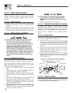
3.2.1 AUTO/OFF/MANUAL SWITCH
Use this three-position switch as follows:
• Set the switch to AUTO for fully automatic opera-
tion. See “Automatic Operation” (Section 3.6).
• Set switch to MANUAL position to crank and start
the generator engine.
• Set switch to OFF position to shut down an operat-
ing engine. With OFF selected, operation will not
be possible.
DANGER
With switch set to AUTO, engine can crank and
start suddenly without warning. Such automatic
start up normally occurs when utility source
voltage drops below a pre-set level. To prevent
possible injury that might be caused by such
sudden starts, set AUTO/OFF/ MANUAL switch
to OFF before working on or around the unit.
Then, place a “DO NOT OPERATE” tag on control
console.
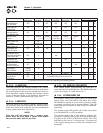
3.2.2 FAULT INDICATOR LEDS
(SEE CHART ON PAGE 14)
These red LEDs turn ON when one or more of the
following engine faults occurs and the engine shuts
down.
• Low Oil Pressure
• Overcrank
• Low Battery
• Overspeed/Engine Speed Signal Fault
• High Coolant Temperature/Low Coolant Level
See Section 1.7 for further explanation of engine pro-
tection functions.
Section 3 - Operation
Liquid-cooled 25 kW Generators