


12
Section 3 - Operation
Liquid-cooled 25 kW Generators
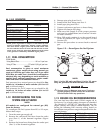
When using maintenance-free batteries, it is not
necessary to check the specific gravity or electrolyte
level. Have these procedures performed at the inter-
vals specified in Section 4, “Maintenance.” A nega-
tive ground system is used. Battery connections are
shown on the wiring diagrams. Make sure all batter-
ies are correctly connected and terminals are tight.
Observe battery polarity when connecting batteries to
the generator set.
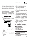
NOTE:
Damage will result if the battery connections are
made in reverse.
2.11 PREPARATION BEFORE START-UP
The instructions in this section assume that the
standby generator has been properly installed, ser-
viced, tested, adjusted and otherwise prepared for
use by a competent, qualified installation contractor.
Be sure to read the “Safety Rules” on pages 2 and 3,
as well as all other safety information in this manual,
before attempting to operate this (and related) equip-
ment.
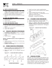
2.11.1 PRIOR TO INITIAL START-UP
Prior to initially starting the generator, it must
be properly prepared for use. Any attempt to
crank or start the engine before it has been
properly serviced with the recommended types
and quantities of engine fluids (oil, coolant, fuel,
etc.) may result in an engine failure.
Before starting the generator for the first time, the
installer must complete the following procedures. For
follow-up maintenance information and/or service
intervals, please refer to Section 4, “Maintenance.”
2.11.2 TRANSFER SWITCH
If this generator is used to supply power to any elec-
trical system normally powered by an electric utility,
the National Electrical Code requires that a transfer
switch be installed. The transfer switch prevents elec-
trical backfeed between two different electrical sys-
tems, (for additional information, see the applicable
transfer switch manual for this unit). The transfer
switch, as well as the generator and other standby
components, must be properly located and mounted
in strict compliance with applicable codes, standards
and regulations.
2.11.3 FUEL SYSTEM
Make sure the fuel supply system to the generator (a)
delivers the correct fuel at the correct pressure and
volume and, (b) is properly purged and leak tested
according to code. No fuel leakage is permitted.
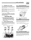
2.11.4 GENERATOR SET LUBRICATION
Check the engine crankcase oil level before operating
and add oil to the proper level – the dipstick “FULL”
mark. Never operate the engine with the oil level
below the dipstick “ADD” mark. See “Specifications”
and “Engine Oil Recommendations”.
NOTE:
This engine is shipped from the manufacturer
with 15W-40 oil. This oil should be changed after
30 hours of operation.
2.11.5 ENGINE COOLANT
Have the engine cooling system properly filled with
the recommended coolant mixture. Check the system
for leaks and other problems. See “Specifications”
and “Coolant”.
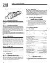
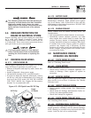
2.11.6 BELT TENSION
Check-the engine-fan belt tension and condition prior
to placing the unit into service and at recommended
intervals. Belt tension is correct when a force of
approximately 22 pounds (10 kg), applied midway
between pulleys, deflects the belt about 3/8- to 5/8-
inches (10 to 16 mm).
2.11.7 ELECTRICAL SYSTEM
Make sure the generator is properly connected to an
approved earth ground and/or ground rod.
Make sure the generator battery is fully charged,
properly installed and interconnected, and ready for
use.
Check to ensure that there are no loose electrical con-
nections. Restrain any loose wires to keep them clear
of any moving generator set components.
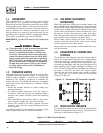
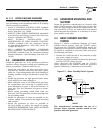
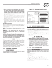
3.1 GTS TRANSFER SWITCH
When required, the pre-packaged standby genera-
tor can be installed with a “GTS” engineered type
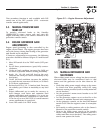
automatic transfer switch. Set DIP switch on engine
control PCB to GTS-type (see Section 3.8).
When using a GTS type transfer switch, it controls
automatic operation and automatic transfer as fol-
lows:
• Solid state circuits in the transfer switch monitor
utility power source voltage.
• When utility source voltage drops below a pre-set
level, transfer switch action signals the genera-
tor to start. The engine then cranks and starts as
controlled by the pre-packaged generator’s Control
Module circuit board.