


14
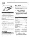
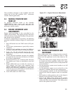
3.2.3 15 AMP FUSE
This fuse protects the control console’s DC control
circuit against electrical overload and is located inside
the control panel. If the fuse has melted open because
of an overload, engine cranking and startup cannot
occur. If the fuse needs to be replaced, use only an
identical 15-amp replacement fuse (type ATO).
3.2.4 5 AMP FUSE
This fuse protects the battery charger against electri-
cal overload and is located inside the control panel.
If the fuse needs to be replaced, use only an identical
5-amp replacement fuse (type ATO).
NOTE:
This fuse will not remove the + battery input
power from the PCB when it opens. This means
the exercise timer will not be reset.
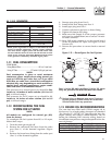
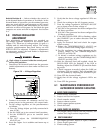
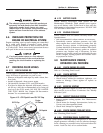
3.2.5 SET EXERCISE TIME SWITCH
This switch allows programming the generator to
start and exercise automatically. “See Weekly Exercise
Cycle” (see Figure 3.3 and Section 3.7).
3.2.6 SYSTEM READY LED
The System Ready LED (green) has two main pur-
poses. First, the LED will be ON when the AUTO/
OFF/MANUAL switch is in the AUTO position, utility
is present, and there are no system alarms. This ON
state indicates the system is fully ready for automatic
operation.
The system ready LED will be OFF when the switch
is in the MANUAL or OFF positions.
The system ready LED is also used to indicate the
presence of utility sensing at the PCB when the switch
is either in the AUTO or MANUAL modes. The LED
will flash at the rate of 1/2 second on, 1/2 second off
if the utility sensing level is below the transfer back
threshold.
Section 3 - Operation
Liquid-cooled 25 kW Generators
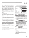
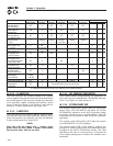
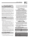
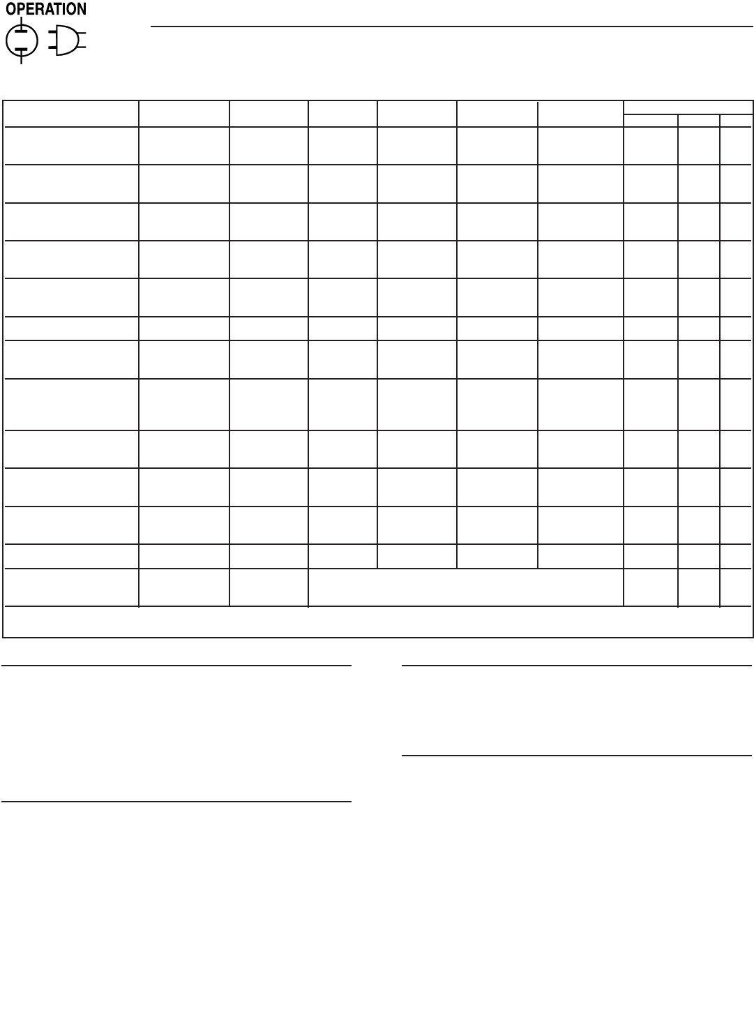
Condition System Low Low High Over Over Switch Position
Ready (Green) Bat (Red) Oil (Red) Temp (Red) Speed (Red) Crank (Red) Manual Auto Off
Generator Switch is OFF X OFF OFF OFF OFF O
in the OFF Mode.
System Ready for ON X OFF OFF OFF OFF O
Automatic Start
Generator Switch is OFF X OFF OFF OFF OFF O
in the MANUAL Mode
Weekly Exerciser X Flashing Flashing Flashing Flashing Flashing O O O
is not set (-----------------------------------1 sec rate---------------------------------------)
Battery Voltage <12V X ON O O O
for >1 minute (Non-latching)
Battery Voltage <6V X ON O O
Unit Shutdown due OFF X ON O O
to Low Oil Pressure
Unit Shutdown due to
High Coolant Temperature OFF X ON O O
or Low Coolant Level
Unit Shutdown due OFF X ON O O
to Engine Overspeed
Unit Failed to Start OFF X ON O O
during it’s Crank Cycle
Utility Voltage is Flashing X O O
<45% of Nominal 1 sec rate
Engine Speed Signal Fault OFF X Flashing O O
Control Board is OFF X The five RED LED’s will turn on one at a time O O O
in GTS Mode
X = indicates that the LED can be ON or OFF depending on the operating conditions.