


7
This generator is not legal for sale in the state of California unless
all CARB evaporative emission requirements are adhered to, and
is not legal for sale in any other state unless certified low-per-
meation fuel line is used to supply the generator with gasoline.
Contact the California Air Resource Board or the Environmental
protection agency for further information. CARB regulations can
be found in 13 CCR §§2750 – 2773; EPA regulations can be
found in 40 CFR Part 90.
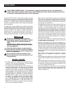
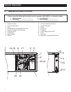
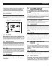
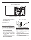
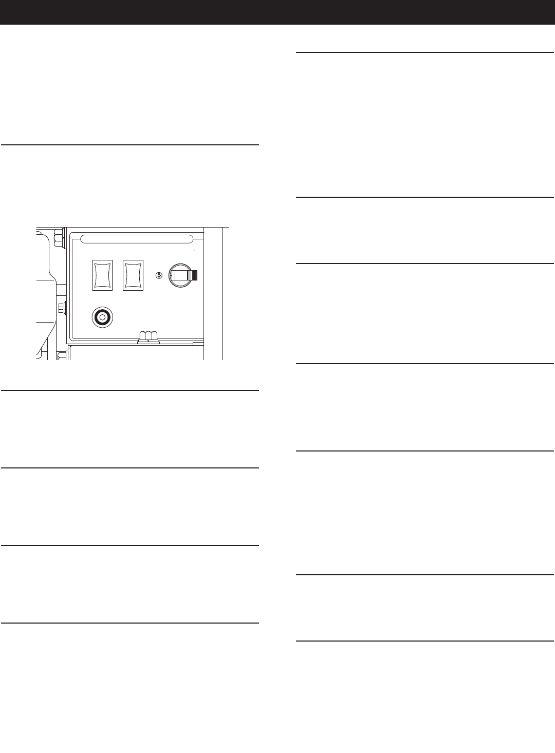
2.1 GENERATOR CONTROL PANEL
The following features are mounted on the generator control panel
(Figure 2.1):
Figure 2.1 – Generator Control Panel
PRIME
FUEL
STOP
START
30A
C.B.
FUSE
CONTROL CENTER
7. 5 A
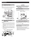
2.1.1 FUEL PRIMER
Before starting a cold engine (if it has not been started in more
than two weeks), press this switch for approximately 10 to 15
seconds to bring fuel from the tank to the carburetor. This rocker
type switch springs back into its original position when released.
2.1.2 START/STOP SWITCH
To crank and start the engine, hold this switch in the START posi-
tion. Release the switch when the engine starts. To stop an operat-
ing engine, press and hold the switch in the STOP position until the
engine shuts off. The switch center position is the RUN position.
2.1.3 FUSE
The fuse protects the engine’s DC control circuit against electrical
overload. If the fuse element has melted open due to overloading,
the engine cannot be cranked. If the fuse must be replaced, use
only an identical replacement.
2.1.4 MAIN BREAKER
The main breaker protects the generator’s AC output circuit against
overload and provides a method of turning OFF the generator’s
120-volt AC output to the vehicle circuits. This generator has
30-amp breaker.
2.2 OPTIONAL REMOTE
START/STOP PANEL
A remote mounted Start/Stop Panel is available that allows start-
ing and stopping the generator engine conveniently from inside
the vehicle.
Order part number 0F0429 or 0F0430, a remote panel that includes
a Start/Stop switch, a generator run lamp, a fuel prime switch, and
an hourmeter. The hourmeter provides a continuous indication of
engine/generator operating time. Use the hourmeter for checking
off periodic maintenance requirements on the unit.
2.3 AUTOMATIC CHOKE
The engine is equipped with an automatic choke that consists of
two main components: a choke solenoid and prechoke.
2.3.1 CHOKE SOLENOID
During engine cranking (Start/Stop switch at START), a solid-state
choke module signals the choke solenoid to activate and cycle
(choke on/choke off) until the engine starts. The choke solenoid
thus opens and closes the carburetor choke valve only when the
engine is cranking. When the engine starts, the choke stops
cycling.
2.3.2 PRECHOKE
The choke system also has a temperature-sensitive metal strip that
adjusts choke valve angle according to ambient temperatures (i.e.,
in cold ambient temperatures, choke valve closes more). Once the
engine starts, an element heats the temperature-sensitive strip to
a normal operating condition, opening the choke valve. This may
take about three minutes in cooler weather.
2.4 BEFORE STARTING THE
ENGINE
NOTE:
Instructions and information in this manual assume the genera-
tor has been properly installed, connected, serviced, tested and
adjusted by a qualified installation technician or installation
contractor.
2.4.1 INSTALLATION
Generator installation must have been properly completed so it
complies with all applicable codes, standards and regulations and
with the manufacturer's recommendations.
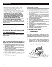
2.4.2 ENGINE LUBRICATION
Have the engine crankcase properly serviced with the recommended
oil before starting. Refer to sections "Engine Oil Requiremtents",
"Checking the Engine Oil Level" and "Changing the Engine Oil and/
or Oil Filter" for oil servicing procedures and recommendations.
Operation