


29
From the junction box, route power supply wires through •
approved conduit to either (a) double-pole, double-throw trans-
fer switch, or (b) approved isolation receptacle. Connecting to
a transfer switch or isolation receptacle must prevent vehicle
electrical circuits from being connected to two different power
supplies at the same time (such as generator and dockside
power).
Conductors must be rated 221° F (105° C) or must be of a •
larger conductor size.
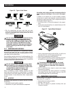
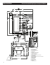
2.6.3 GENERATOR AC CONNECTIONS
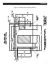
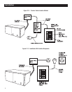
Generator AC output leads (BLACK) “hot” and (WHITE) grounded
neutral come out of the generator as shown in Figure 2.13. There
is also a green lead that connects to ground in the junction box of
the recreational vehicle.
Leads BLACK to WHITE are protected against overload by a
30-amp circuit breaker (CB1). Use this line-to-neutral connection
separately to operate 120-volt, single-phase, 60 Hertz, AC loads
requiring up to 3,600 watts (3.6 kW) of power.
Figure 2.13 – Generator AC Output Leads
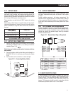
483.1
AC OUTPUT
HARNESS
REMOTE PANEL
CONNECTOR
BATTERY
CONNECTIONS
FUEL FILTER
I
t
r
e
,
e
h
i
t
w
a
n
c
.
-
s
m
,
I
e
W
W
y
s
S
r
o
P
w
e
A
C
N
R
E
G
E
t
TM
Do NOT connect electrical loads in excess
of any circuit breaker rating or problems will
develop with circuit breaker tripping, which
causes a loss of AC output. Also, do NOT
exceed the generator's rated wattage capac-
ity. Add the watts or amperes of all lighting,
appliance, tool and motor loads the generator
will operate at one time. This total should be
less than the unit's rated wattage/amperage
capacity.
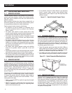
2.6.4 CONDUIT
Route the connections between the generator and the junction box
through approved, flexible conduit. The following general rules
apply:
Cut wiring to the required length and allow extra wire for junc-•
tion box connections.
Carefully prepare conduit ends to prevent sharp edges from •
cutting through wiring insulation.
Route conduit so it does not interfere with generator move-•
ment.
If using metallic conduit, vapor seal the end of the conduit •
where it enters the junction box. Do this because flexible metal-
lic conduit is not vaporproof along its entire length.
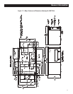
2.6.5 ISOLATING DIFFERENT POWER SOURCES
Connections from the junction box must terminate in a double-
pole, double-throw transfer switch (Figure 2.14). An alternate
method for isolating different power sources is by using an isolat-
ing receptacle (Figure 2.15). Whichever method is used, be certain
that both power sources are NOT connected at the same time.
2.6.6 POWER SUPPLY CORD
The power supply cord must comply with all applicable codes,
standards and regulations. It must be large enough to handle the
full amperage to which it will be subjected.
2.6.7 GROUND FAULT CIRCUIT INTERRUPTERS
The National Electrical Code (NFPA 70, 551-7) requires that
ground fault circuit interrupters (GFCIs) be installed on all external
and some internal electrical receptacles. Contact the dealer for
recommendations.
2.7 BATTERY INSTALLATION
2.7.1 RECOMMENDED BATTERY
Install a battery that meets the following requirements:
The battery must be a 12-volt, automotive type storage bat-•
tery.
For prevailing ambient temperatures above 32° F (0° C), use •
a battery rated 70 amp-hours and capable of delivering 400
cold-cranking amperes.
For prevailing ambient temperatures below 32° F (0° C), use •
a battery rated 95 amp-hours and capable of delivering 400
cold-cranking amperes.
NOTE:
If the battery is to be used to power other vehicle accessories,
as well as start the generator, a battery with a larger capacity
may be needed.
Installation