


28
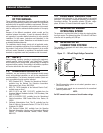
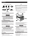
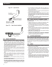
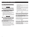
Figure 2.11 - Spark Arrestor
RETAINING
SCREW P/N 056892
SPARK ARRRESTOR
SCREEN P/N 089680
TAILPIPE
P/N 0E0683
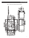
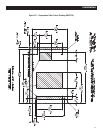
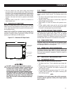
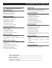
Figure 2.12 — Spark Arrestor Installation
40 [1.58"]
5.5 [7/32"] DRILL
BOTTOM SIDE ONLY
27.4 [1.08"] I.D.
2.5.2 EXHAUST SYSTEM SAFETY
Maintain a clearance of at least 3 inches (76 mm) between •
exhaust system parts and any combustible material (such
as wood, felt, cotton, organic fibers or other like material). If
the 3-inch (76 mm) clearance cannont be maintained, locate,
insulate or shield the exhaust part(s) so that the temperature of
any combustible material is not raised more than 117° F (65°
C) above the ambient air temperature.
Extend the exhaust system at least 1 inch (25 mm) past the •
outer edge of the vehicle. Do not terminate the exhaust system
under the vehicle.
Terminate the exhaust tailpipe such that exhaust gases will not •
be drawn back into the generator compartment and recircu-
lated.
If there is any possibility of the tailpipe or muffler being damaged, •
protect these damage-prone areas by means of a protective
device (such as a skid bar).
Install the generator exhaust system according to safe automo-•
tive practices.
Use enough exhaust system hangers to prevent any part of the •
system from being dislocated.
Use exhaust system parts recommended by the manufacturer. •
Using unapproved exhaust mufflers and exhaust system parts
is the responsibility of the person(s) installing such unauthor-
ized parts.
Do not terminate the exhaust system under any opening, win-•
dow or vent that can be opened or is not permanently sealed
from the vehicle interior.
Exhaust piping must be large enough to prevent excessive back •
pressure on the generator engine.
Never tee the generator engine exhaust pipe into the vehicle •
engine exhaust piping. This causes excessive back pressure on
the generator engine. Also, water from one engine can damage
the other engine.
Plan exhaust system installation carefully. Comply with all appli-•
cable codes, standards and regulations.
2.6 ELECTRICAL CONNECTIONS
The following general rules apply to electrical connections in a
recreational vehicle:
Qualified electricians who are familiar with applicable codes, •
standards and regulations should install electrical wiring.
The wiring should comply with codes, standards and regula-•
tions. The National Electrical Code (NFPA 70), and state and
local codes apply.
Switches and circuit breakers should be of a type approved for •
use in recreational vehicles and must be mounted and installed
to prevent damage from road shock.
Wiring must be of adequate size, have approved insulative •
qualities and be properly supported.
Conduit and wire openings into the generator compartment •
(if used) must be vapor-sealed to prevent entry of flammable,
explosive or poisonous gases into the vehicle.
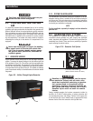
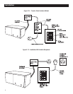
2.6.1 ELECTRICAL JUNCTION BOX
Install an approved, square electrical junction box with a blank
cover on the interior or exterior wall of the area planned for installa-
tion of the generator (NOT on the generator). Route the generator's
AC output leads into this junction box through approved flexible
conduit. This is the point of first termination for generator AC
output leads.
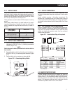
2.6.2 WIRING
Wiring should be of stranded copper to reduce the chance that •
vibration may cause breakage.
Wire gauge size should be large enough to handle at least 115 •
percent of the installed generator's rated maximum current.
Neutral conductors must be the same size as other leg wires.•
Route power supply conductors from generator AC output leads •
(white), (black) and the green ground wire through approved
flexible conduit to the electrical junction box on the compart-
ment wall.
If flexible metal conduit is used between the generator and the •
compartment junction box, the conduit end that terminates the
compartment junction box must be vapor-sealed. Flexible metal
conduit is NOT vapor tight along its entire length.
Installation