


31
2.7.2 BATTERY CABLES
Using battery cables that are too long or too small in diameter
may cause a drop in voltage, which causes starting problems. For
the best cold weather starting, the voltage drop between battery
terminals and the generator connection point should not exceed
0.12 volts per 100 amperes of cranking current.
These generators are rated at about 100 DC amperes of cranking
current.
Select battery cables based on (a) cable length and (b) prevail-
ing ambient temperatures. Generally, the longer the cable and the
colder the weather, the larger the cable size must be, as shown in
the chart.
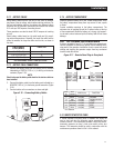
CABLE LENGTH
in Feet (Meters)
CABLE SIZE
0 to 10 (0 to 3) 2*
11 to 15 (3.4 to 4.5) 0
16 to 20 (4.5 to 6) 000
* For warm weather, use No. 2 cable up to 20 feet.
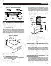
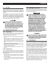
2.7.3 BATTERY CABLE CONNECTIONS
1. Connect the battery cable from the battery post or terminal
indicated by a POSITIVE, POS or (+) to the lug on the starter
contactor (Figure 2.16).
NOTE:
Check to be sure the battery cable boot for the starter cable has
been installed.
2. Connect the battery cable from the battery post indicated by a
NEGATIVE, NEG or (-) to the frame ground connection (Figure
2.16).
3. Connect cables so the connectors are clean and tight.
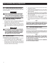
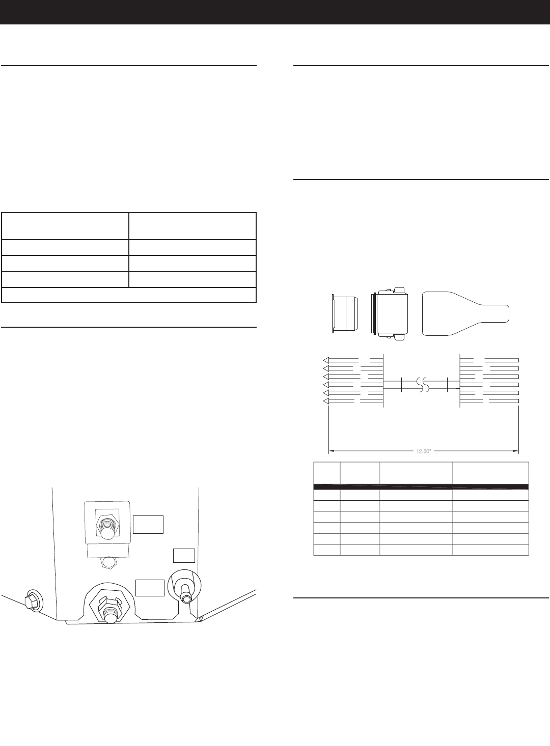
Figure 2.16 – Connecting Battery Cables
NEG
FUEL
POS
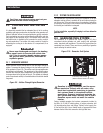
2.7.4 BATTERY COMPARTMENT
Install the generator battery in its own, vented compartment. Place
the battery compartment away from any source of heat, sparks
or flame.
Provide ventilation openings in the battery compartment. The
minimum size of openings should be 2 square inches at the top
of the compartment. Mount the battery on a strong, rigid support-
ing structure, where leaks and spills of battery fluid will not cause
damage.
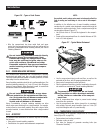
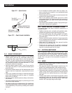
2.8 OPTIONAL ACCESSORIES
A plug-in receptacle (Figure 2.17) is provided on the generator set.
Use this receptacle to connect an optional remote-mounted start/
stop panel to the generator. Installation of such a panel will permit
starting and stopping the generator engine from any convenient
location inside the vehicle.
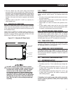
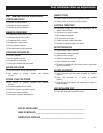
Figure 2.17 – Remote Panel Plug-in Receptacle
12.00"
14
0
17
1
5
1
8
14A
1
3
2
5
4
6
0
14
17
1
8
14A
1
5
1
5
17
14A
1
8
14
0
N
o.
WIRE
WIRE
CO
L
OR
RED
YELL
OW
O
RAN
GE
WHITE
BL
UE
BR
O
W
N
12.0
(
305
)
LENGTH
(
mm
)
12.0
(
305
)
12.0
(
305
)
12.0
(
305
)
12.0
(
305
)
12.0
(
305
)
FUNCTION
GROUND
ENGINE RUN SIGNAL
12 VDC
START
STOP
PRIME
P
/
N:
0
D
9099
-
B
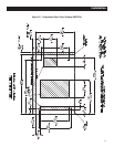
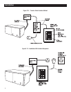
2.8.1 REMOTE START/STOP PANEL
A remote mounted Start/Stop panel is available that allows the
user to start and stop the generator engine conveniently from
inside the vehicle. The remote panel includes a Start/Stop switch,
hourmeter, generator run lamp, a fuel prime switch, and a wire
harness. The hourmeter should be used in conjunction with the
maintenance operations found in Part I of this manual.
Installation