


Generac
®
Power Systems, Inc. 7
1.6 SYSTEM SET LED
The “System Set” LED is lit when all of the following
conditions are true:
1. The AUTO/OFF/MANUAL switch is set to the
AUTO position.
2. The UTILITY voltage being supplied to the unit is
being sensed by the PCB. If the UTILITY sense
voltage is not connected to the unit or if it is
below 168 volts AC, then the System Set light will
flash rapidly. This indicates that if the
AUTO/OFF/MANUAL switch is placed in the Auto
position , the generator will start.
3. The “Not In Auto” dip switch is set to the OFF
position on the control board.
4. No alarms are present, for example, low oil pres-
sure, high temperature, etc.
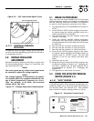
1.7 FUEL REQUIREMENTS
AND RECOMMENDATIONS
With LP gas, use only the vapor withdrawal
system. This type of system uses the vapors formed
above the liquid fuel in the storage tank.
The engine has been fitted with a fuel carburetion
system that meets the specifications of the 1997
California Air Resources Board for tamper-proof dual
fuel systems. The unit will run on natural gas or LP
gas, but it has been factory set to run on natural gas.
Should the primary fuel need to be changed to LP
gas, the fuel system needs to be reconfigured. See
Section 1.9 for instructions on reconfiguration of the
fuel system.
Recommended fuels should have a Btu content of at
least 1,000 Btus per cubic foot for natural gas; or at
least 2,520 Btus per cubic foot for LP gas. Ask the
fuel supplier for the Btu content of the fuel.
Required fuel pressure for natural gas is 5 inches to
7 inches water colum (0.18 to 0.25 psi); and for
liquid propane, 11 inches to 14 inches of water
column (0.4 to 0.5 psi).
NOTE:
Any piping used to connect the generator to the
fuel supply should be of adequate size to ensure
the fuel pressure NEVER drops below 4 inches
water colum for natural gas or 10 inches water col-
umn for liquid propane for all load ranges.
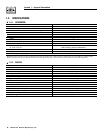
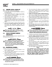
1.8 FUEL CONSUMPTION
* Natural gas is in cubic feet per hour.
** LP is in gallons per hour/cubic feet per hour.
Gaseous fuels such as natural gas and liquid
propane (LP) gas are highly explosive. Even the
slightest spark can ignite such fuels and cause
an explosion. No leakage of fuel is permitted.
Natural gas, which is lighter than air, tends to
collect in high areas. LP gas is heavier than air
and tends to settle in low areas.
1.9 RECONFIGURING THE
FUEL SYSTEM
To reconfigure the fuel system from NG to LP,
follow these steps:
NOTE:
The primary regulator for the propane supply is
NOT INCLUDED with the generator. A fuel pres-
sure of 11 to 14 inches of water column (0.4 to 0.5
psi) to the fuel inlet of the generator MUST BE
SUPPLIED.
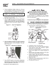
1. Turn off the gas supply. (if connected)
2. Open the roof and remove the door.
3. Remove the battery. (if installed)
4. Remove the engine air in baffle located on the left-
hand side of the battery compartment. Two M6
screws are located on top of the baffle and two
M6 screws are located on the inside of the baffle
towards the back.
5. Remove the small hose clamp and hose from the
fuel regulator. It may be necessary to pry the hose
off of the brass fitting using a screwdriver to gen-
tly lift up the hose edge.
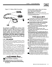
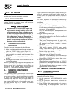
6. Remove the small brass hose fitting from the reg-
ulator casting.
7. Place the small fuel jet, thread side first, into the
threaded hole originally occupied by the brass
hose fitting (Figure 1.4).
8. Using a short No. 2 Phillips screw driver, thread
the small fuel jet into the regulator casting. Do
not over tighten.
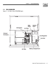
Figure 1.4 - Demand Regulator
BRA
SS
H
OS
E
FITTIN
G
IDLE
C
IR
CU
I
T
P
O
R
T
U
1
T
TAP
1
/8
NP
T
BRA
SS
H
OS
E
FITTIN
G
F
U
EL H
OSE
S
MAL
L
F
U
EL
J
E
T
RE
GU
LAT
OR
H
OUS
IN
G
P
O
R
T
AD
JUS
TE
R
SC
REW
S
OU
TLET P
O
RT
S
Section 1 — General Information
Air-cooled 8.5 kW Generator
Model # Nat. Gas (*) LP Vapor (**)
1/2 Load Full Load 1/2 Load Full Load
004692-1 114 170 1.33/45.8 1.98/72.5