


14 Generac
®
Power Systems, Inc.
Section 3 — Operation
Air-cooled 8.5 kW Generator
3.2.2 “OFF” POSITION
This switch position shuts down the engine. This
position also prevents automatic operation.
3.2.3 “MANUAL” POSITION
Set the switch to Manual to crank and start the
engine. Transfer to standby power will not occur
unless there is a utility failure.
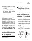
With the switch set to AUTO, the engine may
crank and start at any time without warning.
Such automatic starting normally occurs when
utility power source voltage drops below a pre-
set level or during the normal exercise cycle. To
prevent possible injury that might be caused by
such sudden starts, always set the switch to
OFF and remove the fuse before working on or
around the generator or transfer switch. Then,
place a “Do Not Operate” tag on the generator
panel and on the transfer switch.
3.3 AUTOMATIC TRANSFER
OPERATION
To select automatic operation, do the following:
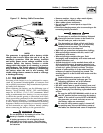
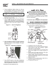
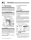
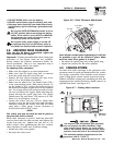
1. Make sure the transfer switch main contacts are
set to their UTILITY position, i.e., loads connect-
ed to the UTILITY power source (Figure 3.2).
2. Be sure that normal UTILITY power source volt-
age is available to transfer switch terminal lugs
N1 and N2.
3. Set the generator’s AUTO/OFF/MANUAL switch to
AUTO.
4. Set the generator’s main circuit breaker to its ON
(or closed) position.
With the preceding steps complete, the generator will
start automatically when utility source voltage drops
below a preset level. After the unit starts, loads are
transferred to the standby power source. Refer to
Section 3.4, “Sequence of Automatic Operation”.
3.4 SEQUENCE OF AUTOMATIC
OPERATION
The generator’s control panel houses a control logic
circuit board. This board constantly monitors utility
power source voltage. Should that voltage drop below
a preset level, circuit board action will signal the
engine to crank and start. After the engine starts, the
circuit board signals the transfer switch to activate
and connect load circuits to the standby power sup-
ply (load terminal lugs T1/T2 connect to terminal
lugs E1/E2).
Upon restoration of utility source voltage above a pre-
set level, generator circuit board action signals the
transfer switch to transfer loads back to that power
supply. After retransfer, the engine is signalled to shut
down.
The actual sequence of operation is controlled by
sensors and timers on a control logic circuit board,
as follows:
A. Utility Voltage Dropout Sensor
• This sensor monitors UTILITY source voltage.
• If utility source voltage drops below about 60 per-
cent of the nominal supply voltage, the sensor
energizes a 15-second timer.
• Once the timer has expired, the engine will crank
and start.
B.Engine Warm-up Time Delay
• This mechanism lets the engine warm up for
about 10 seconds before the load is transferred
to a standby source.
C.Standby Voltage Sensor
• This sensor monitors generator AC output volt-
age. When the voltage has reached 50 percent of
the nominal rated voltage, transfer to standby
can occur.
D.Utility Voltage Pickup Sensor
• This sensor monitors UTILITY power supply
voltage. When that voltage is restored above 80
percent of the nominal source voltage, a retrans-
fer time delay starts timing.
E.Retransfer Time Delay
• This timer runs for about 15 seconds.
• At end of a 15-second delay, circuit board action
de-energizes transfer relay in the transfer switch.
• Retransfer to UTILITY power source then occurs.
F. Engine Cool-down Timer
• When the load is transferred back to UTILITY
power source, the engine cool-down timer starts
timing.
• The timer will run for about one minute, and the
generator will then shut down.
3.5 MANUAL TRANSFER OPERATION
3.5.1 TRANSFER TO GENERATOR
POWER SOURCE
To start the generator and activate the transfer switch
manually, proceed as follows:
1. Set the generator’s AUTO/OFF/MANUAL switch
to OFF.
2. Set the generator’s main circuit breaker to its
OFF (or open) position.
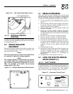
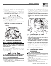
3. Turn OFF the utility power supply to the transfer
switch using the means provided (such as a
utility main line circuit breaker).
!