


10 Generac
®
Power Systems, Inc.
2.1 BEFORE INITIAL START-UP
Before starting, complete the following:
1. Set the generator's AUTO/OFF/MANUAL switch to
the OFF position.
2. Turn OFF the utility power supply to the transfer
switch using the means provided (such as the
utility main line circuit breaker).
3. Turn OFF all loads connected to the tranfer
switch terminals T1 and T2.
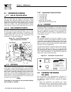
4. Check the engine crankcase oil level and, if nec-
essary, fill to the dipstick FULL mark with the
recommended oil. Do not fill above the FULL
mark.
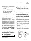
5. Check the fuel supply. Gaseous fuel lines must
have been properly purged and leak tested in
accordance with applicable fuel-gas codes. All
fuel shutoff valves in the fuel supply lines must be
open.
Never operate the engine with the oil level
below the “Add” mark on the dipstick. Doing
this could damage the engine.
2.2 CHECK TRANSFER SWITCH
OPERATION
Refer to Section 3.5, of the owner’s manual for man-
ual operation procedures.
Do not attempt manual transfer switch opera-
tion until all power voltage supplies to the
transfer switch have been positively turned off.
Failure to turn off all power voltage supplies
will result in extremely hazardous and possibly
fatal electrical shock.
2.3 ELECTRICAL CHECKS
Complete electrical checks as follows:
1. Set the generator's main circuit breaker to its
OFF (or open) position.
2. Turn OFF all loads connected to the transfer
switch terminals T1 and T2.
3. Turn on the UTILITY power supply to the trans-
fer switch using the means provided (such as a
utility main line circuit breaker).
The transfer switch is now electrically “hot.”
Contact with “hot” parts will result in extreme-
ly hazardous and possibly fatal electrical shock.
Proceed with caution.
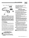
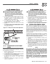
4. Use an accurate AC voltmeter to check UTILITY
power source voltage across transfer switch ter-
minals N1 and N2. Nominal line-to-line voltage
should be 240 volts AC.
5. Check UTILITY power source voltage across ter-
minals N1 and the transfer switch neutral lug;
then across terminal N2 and neutral. Nominal
line-to-neutral voltage should be 120 volts AC.
6. When certain that UTILITY supply voltage is com-
patible with transfer switch and load circuit rat-
ings, turn OFF the UTILITY power supply to the
transfer switch.
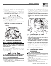
7. On the generator panel, set the AUTO/OFF/MAN-
UAL switch to MANUAL. The engine should crank
and start.
8. Let the engine warm up for about five minutes to
allow internal temperatures to stabilize. Then, set
the generator’s main circuit breaker to its ON (or
closed) position.
Proceed with caution! Generator power voltage
is now supplied to the transfer switch. Contact
with live transfer switch parts will result in
dangerous and possibly fatal electrical shock.
9. Connect an accurate AC voltmeter and a frequen-
cy meter across transfer switch terminal lugs E1
and E2. Voltage should be 242-252 volts; fre-
quency should read about 61-63 Hertz.
10. Connect the AC voltmeter test leads across termi-
nal lug E1 and neutral; then across E2 and neu-
tral. In both cases, voltage reading should be 121-
126 volts AC.
11. Set the generator’s main circuit breaker to its
OFF (or open) position. Let the engine run at no-
load for a few minutes to stabilize internal engine
generator temperatures.
12. Set the generator's AUTO/OFF/MANUAL switch to
OFF. The engine should shut down.
NOTE:
It is important not to proceed until certain that
generator AC voltage and frequency are correct
and within the stated limits. Generally, if both AC
frequency and voltage are high or low, the engine
governor requires adjustment. If frequency is cor-
rect, but voltage is high or low, the generator’s
voltage regulator requires adjustment.
DANGER
DANGER
!
Section 2 — Post Installation Start-up and Adjustments
Air-cooled 8.5 kW Generator