


Generac
®
Power Systems, Inc. 19
• DO NOT SMOKE when near the battery;
• DO NOT cause flame or spark in battery area; and
• Discharge static electricity from body before touch-
ing the battery by first touching a grounded metal
surface.
Be sure the AUTO/OFF/MANUAL switch is set to
the OFF position before connecting the battery
cables. If the switch is set to AUTO or MANUAL,
the generator can crank and start as soon as
the battery cables are connected.
Be sure the utility power supply is turned off,
or sparking may occur at the battery posts as
the cables are attached and cause an explosion.
4.8 ADJUSTING VALVE CLEARANCE
After the first 50 hours of operation, adjust the
valve clearance in the engine.
Important: If feeling uncomfortable about doing this
procedure or the proper tools are not available,
please contact the Generac Authorized Dealer for
service assistance. This is a very important step to
insure the longest life for the engine.
To adjusting valve clearance:
• Make sure the engine is at room temperature.
• Make sure that the spark plug wire is removed
from the spark plug and out of the way.
• Remove the four screws attaching the valve cover
with a #2 or #3 phillips screwdriver.
• Make sure the piston is at Top Dead Center (TDC)
of its compression stroke (both valves closed). To
get the piston at TDC, remove the intake screen at
the front of the engine to gain access to the flywheel
nut. Use a large socket and socket wrench to rotate
the nut and hence the engine. While watching the
piston through the spark plug hole. The piston
should move up and down. The piston is at TDC
when it is up as high as it can go.
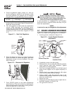
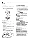
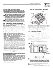
• Loosen the rocker jam nut. Use an 10mm allen
wrench to turn the pivot ball stud while checking
clearance between the rocker arm and the valve
stem with a feeler gauge. Correct clearance is
0.002-0.004 inch (0.05-0.1 mm).
NOTE:
The rocker arm jam nut must be held in place as
the pivot ball stud is turned.
When valve clearance is correct, hold the pivot ball
stud in place with the allen wrench and tighten the
rocker arm jam nut. Tighten the jam nut to 174
in/lbs. torque. After tightening the jam nut, recheck
valve clearance to make sure it did not change.
• Install new valve cover gasket.
• Re-attach the valve cover.
Figure 4.6 - Valve Clearance Adjustment
NOTE:
Start all four screws before tightening or it will not
be possible to get all the screws in place. Make
sure the valve cover gasket is in place.
• Re-attach the spark plug wire to the spark plug.
• Repeat the process for the other cylinder.
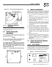
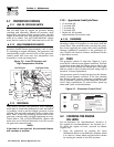
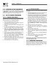
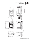
4.9 COOLING SYSTEM
Air inlet and outlet openings in the generator com-
partment must be open and unobstructed for contin-
ued proper operation. This includes such obstruc-
tions as high grass, weeds, brush, leaves and snow.
Without sufficient cooling and ventilating air flow, the
engine/generator quickly overheats, which causes it to
quickly shut down. (see Figure 4.7)
Figure 4.7 – Cooling Vent Locations
The exhaust from this product gets extremely
hot and remains hot after shutdown. High
grass, weeds, brush, leaves, etc. must remain
clear of the exhaust. Such materials may ignite
and burn from the heat of the exhaust system.
The maximum ambient temperature for the
generator is 48.9° C (104° F).
!
Jam Nut
Pivot Ball
Stud
Rocker
Arm
Valve
Stem
!
Section 4 — Maintenance
Air-cooled 8.5 kW Generator