


9. Apply thread sealant to the threads of the hose fit-
ting and replace it into the regulator body.
10. Re-attach the small hose and hose clamp and
tighten as necessary.
11. Replace the engine air in baffle using the four M6
screws.
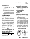
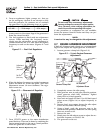
12. Identify both brass adjustment screws on the reg-
ulator.
NOTE:
One adjustment screw can be accessed from the
front of the unit and the second can be accessed
from the back of the unit enclosure by removing
the plastic hole plug. The screw can be turned
with a long flat blade screwdriver.
13. To adjust the system to run on LP fuel, turn
BOTH adjuster screws 1/2 TURN CLOCKWISE.
The system should now be set for maximum
power and best perfomance. DO NOT, UNDER
ANY CIRCUMSTANCES, REMOVE THE SET
PINS FROM THE REGULATOR HOUSING.
THIS WILL VOID THE WARRANTY.
14. It may be necessary to make minor adjustments
to the preset adjustment screw settings to achieve
maximum power, particularly at higher altitudes.
If experiencing problems with the unit producing
maximum power, follow the procedure in Section
2.6 (Adjusting the Fuel Regulator).
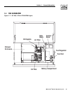
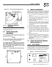
1.10 LOCATION
1.10.1 GENERATOR
Install the generator set, in its protective enclosure,
outdoors, where adequate cooling and ventilating air
is always available. Consider these factors:
• Install the unit where air inlet and outlet openings
will not become obstructed by leaves, grass, snow,
etc. If prevailing winds will cause blowing or drift-
ing, consider using a windbreak to protect the unit.
• Install the generator on high ground where water
levels will not rise and endanger it.
• Allow sufficient room on all sides of the generator
for maintenance and servicing. A good rule is to
allow three feet of space on all sides.
• Where strong prevailing winds blow from one
direction, face the generator air inlet openings to
the prevailing winds.
• Install the generator as close as possible to the fuel
supply, to reduce the length of piping.
• Install the generator as close as possible to the
transfer switch. HOWEVER, REMEMBER THAT
LAWS OR CODES MAY REGULATE THE DIS-
TANCE.
1.10.2 TRANSFER SWITCH
The transfer switch shipped with this generator is
rated 100 amps maximum at 120/240 volts AC single
phase. The enclosure of the transfer switch is NEMA
1. This type of enclosure is intended for indoor use
only. Follow these rules:
• Install the transfer switch indoors on a firm, stur-
dy supporting structure.
• To prevent switch distortion, level the switch if nec-
essary. This can be done by placing washers
between the switch enclosure and mounting surface.
• Never install the switch where water or any corro-
sive substance might drip onto the enclosure.
• Protect the switch at all times against excessive
moisture, dust, dirt, lint, construction grit and cor-
rosive vapors.
1.11 BATTERY INSTALLATION
Fill the battery with the proper electrolyte fluid if nec-
essary and have the battery fully charged before
installing it.
Before installing and connecting the battery, complete
the following steps:
1. Set the generator's AUTO/OFF/MANUAL switch to
OFF.
2. Turn off utility power supply to the transfer
switch.
If the AUTO/OFF/MANUAL switch is not set to
its OFF position, the generator can crank and
start as soon as the battery cables are connect-
ed. If the utility power supply is not turned off,
sparking can occur at the battery posts and
cause an explosion.
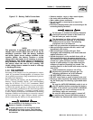
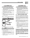
Battery cables were factory connected at the genera-
tor (Figure 1.5). Connect cables to battery posts as
follows:
3. Connect the red battery cable (from starter con-
tactor) to the battery post indicated by a positive,
POS or (+).
4. Connect the black battery cable (from frame
ground) to the battery post indicated by a nega-
tive, NEG or (—).
NOTE:
Damage will result if battery connections are made
in reverse.
DANGER
◆
◆
Section 1 — General Information
Air-cooled 8.5 kW Generator
8 Generac
®
Power Systems, Inc.