


Generac
®
Power Systems, Inc. 13
Section 3 — Operation
Air-cooled 8.5 kW Generator
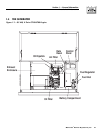
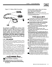
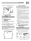
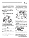
Figure 2.4 — Full Load Speed Adjust Screw
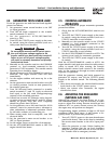
2.7.1 ADDITIONAL CORROSION
PROTECTION
Periodically spray all engine linkage parts and brack-
ets with corrosion inhibiting spray such as WD-40 or
a comparable product.
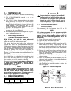
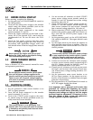
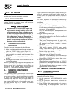
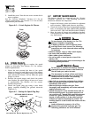
2.8 VOLTAGE REGULATOR
ADJUSTMENT
With the frequency between 62-63 Hertz, slowly turn
the slotted potentiometer (Figure 2.5) until line volt-
age reads 244-252 volts.
NOTE:
The access panel on top of the control panel must
be removed to adjust the voltage regulator.
NOTE:
The voltage regulator is housed above the genera-
tor's control panel. The regulator maintains a volt-
age in direct proportion to frequency at a 2-to-1
ratio. For example, at 62 Hertz, line-to-neutral
voltage will be 124 volts.
Figure 2.5 – Voltage Adjustment Potentiometer
3.1 BREAK-IN PROCEDURE
Once the unit has been installed and all electrical
checks have been made, it is strongly recommended
that the following “Break-in Procedure” be completed
to ensure correct generator operation in the future.
1. Set the generator’s AUTO/OFF/MANUAL switch to
AUTO.
2. Turn OFF the UTILITY power supply to the trans-
fer switch using the means provided (such as a
utility main line circuit breaker).
3. The unit will start, and the transfer switch will
transfer to standby.
4. Using the transfer switch’s built-in emergency
load center, turn on circuits to load the generator
to approximately 25% rated load and run the unit
for one hour.
5. Run the unit for one hour at 50% rated load.
6. Run the unit for one hour at 75% rated load.
7. Run the unit for one hour at 100% rated load.
8. Turn ON the UTILITY power supply to the trans-
fer switch, which will allow the transfer switch to
transfer back to UTILITY power. The unit will
continue to run for one minute and then shut
down.
9. Allow the unit to cool.
10. Drain the oil and remove the oil filter. Replace the
oil filter according to Section 4.4, “Changing the
Oil Filter”. Replace the oil with synthetic oil as
recommended in Section 4.3, “Changing the
Engine Oil”.
11. The generator is now ready for service.
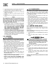
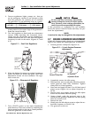
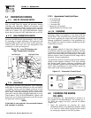
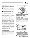
3.2 USING THE AUTO/OFF/MANUAL
SWITCH (FIGURE 3.1)
3.2.1 “AUTO” POSITION
Selecting this switch position activates fully automat-
ic system operation. It also permits starting and exer-
cising the engine every seven days with the setting of
the exercise timer (see Section 3.6). This position
also is used for remote starting, when it is set up.
Figure 3.1 – Generator Control Panel
HIGH TEMP.
OVER SPEED
LOW OIL
SYSTEM SET
OVER CRANK
MAN.
SET
OFFAUTO
15A
FUSE
EXERCISE
TIME
R
POWER SYSTEMS, INC.
Locate your nearest dealer at:
R
FUSE
5A
EXERCISE RNOT SET
NOUTILITYSE NSE
4FLASHING RED LEDS=
FLASHINGGREEN LED=
◆
Full Load Speed Adjust Screw