


■■
GE Zenith Controls 3
■■
ZTX Operation and Maintenance Manual (72R-1000)
Installation
(cont’d)
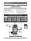
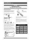
Control Connections
Connecting Engine Start may cause Generator to
start. Before connecting, turn Generator OFF.
With the Generator breaker open and the Generator
control switch off, install the Generator start connections.
Note:
N = Utility Position
E = Generator Position
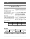
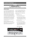
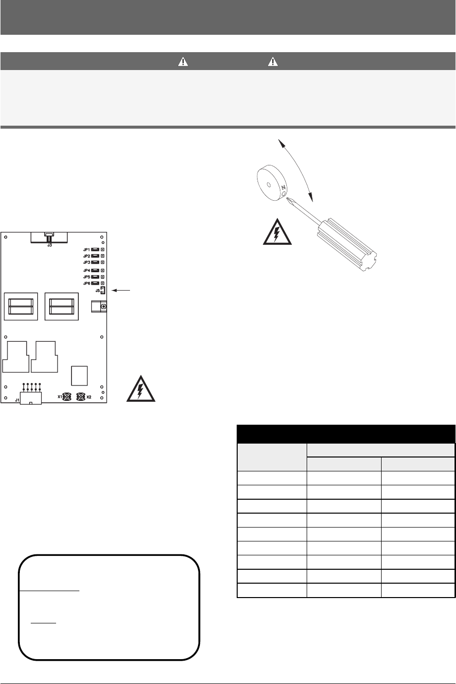
Manual operation is possible for maintenance purposes only.
Manual operation of the switch can be checked before it
is operated electrically.
With all power off, insert a Phillips screwdriver or equivalent
size tool into the manual operator socket and operate
the transfer switch between the Utility and Generator
positions. The transfer switch should operate smoothly
without binding. Return the switch to the Utility position,
remove the screwdriver.
Figure 4
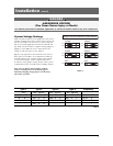
Table 2
Tightening Torque for Lugs
Socket Size
Across Flats
Torque
Lb. - In. Lb. - Ft.
451/8 4
1005/32 8
1203/16 10
1507/32 12
2001/4 17
2755/16 23
3753/8 31
5001/2 42
6009/16 50
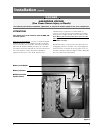
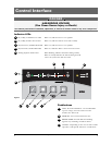
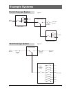
The engine-start terminals are clearly identified by a
label on the microcontroller backplate. In the case of
manual transfer switches, or in other applications not
requiring the microprocessor, clearly marked terminal
blocks are provided in the upper left corner of the control
panel for the engine start control wires.
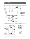
Terminals for field connections to the A3 Emergency
auxiliary contacts and the A4 Normal auxiliary contacts
are also provided. These terminals are clearly marked
and appear on the side of the power panel. On 400 amp
metal frame units these terminals appear on the bracket
above the operator handle.
DANGER
HAZARDOUS VOLTAGE
(Can Cause Severe Injury or Death)
Turn OFF all power before installation, adjustment, or removal of transfer switch or any of its components.
Figure 3
g
SERIAL NUMBER:
RA
TING
: VOLTS -
AMPS -
SYSTEM VOLTS:
MODEL NUMBER:
HZ -
PHASE -
GE Zenith Controls
JP
Battery
Connection
Figure 2