


■■
2 GE Zenith Controls
■■
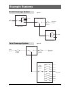
ZTX Operation and Maintenance Manual (72R-1000)
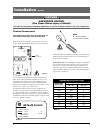
GENERAT
OR
TERMINAL
S
N
BR
U
TILIT
Y
TERMINAL
S
LOAD
TERMINALS
T1
T2
T
3
N1
N
3
E1
E
3
E2
N2
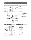
T = Load N = Utilit
y
E = Generato
r
OPTIONAL A4 CONTACT
T
I
ON
OPERATES WHEN IN
ERA
T
UTILITY POSITION
ILIT
Y
OPTIONAL A3 CONTACT
TI
ON
OPERATES WHEN IN
ERA
T
GENERATOR POSITION
NER
A
SWITCH
POSITION
INDICAT
OR
JP
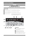
Install
load
cables
first.
Tip!
Table 1
Screw Type Terminals for External Power Connections
Switch Size
(Amps)
40
80
100
150
Utility, Generator and Load Terminals
1 #8 to 3/0 AWG
Cable Per Pole Range of Wire Sizes
1 #8 to 3/0 AWG
1 #8 to 3/0 AWG
1 #8 to 3/0 AWG
Fully Rated Neutral Bar (When Required)
3 #8 to 1/0 AWG
No. of Cables Range of Wire Sizes
3 #8 to 1/0 AWG
3 #8 to 1/0 AWG
3 #8 AWG to 300 MCM
200, 225, 250*
300, 400
1 #6 AWG to 250 MCM
1 #4 AWG to 600 MCM
3 #6 AWG to 300 MCM
3 #4 AWG to 300 MCM
* IEC Rating Only
Installation
(cont’d)
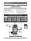
Figure 1 - Power Panel
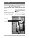
Power Connections
GE Zenith transfer switches are supplied with UL listed
solderless screw type terminals as standard for the
Normal, Emergency and Load power connections.
Table 1 lists the number and sizes of cable lugs supplied
as standard for each switch amp rating.
DANGER
HAZARDOUS VOLTAGE
(Can Cause Severe Injury or Death)
Turn OFF all power before installation, adjustment, or removal of transfer switch or any of its components.
Connect the Normal, Emergency, and Load conductors
to the clearly marked terminals on the transfer switch.
Remove surface oxides from cables by cleaning with a
wire brush. Verify that all connections are correct before
tightening the lugs. All cable lug connections must be
tightened to the proper torque values as shown in Table 2.
NOTE: Do not run cables or wiring behind
front-connected transfer switches.