


■■
GE Zenith Controls 5
■■
ZTX Operation and Maintenance Manual (72R-1000)
Functional Test
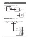
Functional testing of the automatic transfer switch
(ATS) is described in this section. Before proceeding,
read and understand all instructions and review the
operation of all accessories provided.
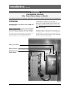
To begin the test, close the Utility source circuit breaker.
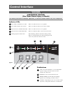
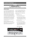
Referring to Figure 7, the controller will illuminate the
Utility Available LED when proper voltage is sensed. If
the ATS mechanism is set on S1, the S1 position LED
will also light.. Verify the phase to phase voltages at the
Utility line terminals.
Next, close the Generator source breaker and start the
engine generator. The S2 (Generator) Available LED
will illuminate when proper voltage and frequency levels
are sensed. After both sources have been verified, shut
down the engine generator, and put the generator’s start
control in the automatic position. Complete the visual
inspection of the transfer switch, and replace the cabinet
cover (or close the cabinet door).
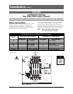
Simulate a utility outage by opening the S1 Utility side
breaker. The delay to engine start timer (P) begins its
timing cycle. After the P timer has completed its timing
cycle, the engine start contacts close to start the generator.
When generator voltage and frequency reach the preset
restore points (see Table 4) the S2 Available LED illumi-
nates. Simultaneously, the delay to generator timer (W)
begins its timing cycle. When the W time delay is com-
pleted the ATS will transfer to Generator, the S1 position
LED goes off, and the S2 position LED illuminates.
Reclose the Utility breaker to retransfer to utility. The
delay to utility timer (T) begins its timing cycle (Table
3). When the T timer has completed its timing cycle, the
ATS will transfer. The optional S2 position LEDs go off,
and the S1 position LED illuminates. The delay engine
stop timer (U) begins its timing cycle. The generator
runs unloaded for the duration of the U timing cycle.
When the timer completes its timing cycle, the generator
will stop. The S2 Available LED goes off.
Installation
(cont’d)
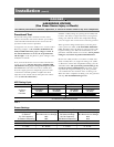
Table 3
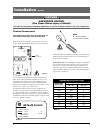
DANGER
HAZARDOUS VOLTAGE
(Can Cause Severe Injury or Death)
Turn OFF all power before installation, adjustment, or removal of transfer switch or any of its components.
ATS Timing Cycle
Action P Timer W Timer T Timer U Timer
P - 5 sec. W - 20 sec. T - 5 min. U - 5 min.
S1 Fail or Time Delay Time Delay Time Delay Time Delay
Test or S2 Start S2 Stable S1 Stable S2 Stop
Exerciser
Transfer to S2 Retransfer to S1 Engine Cool-Down
S1 returns or Test/Exerciser Ends
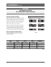
Table 4
Preset Settings
Utility Generator
S1 Fail Voltage 80% Nominal Line Voltage S2 Fail Voltage 80% Nominal Line Voltage
S1 Restore 90% Nominal Line Voltage S2 Restore Voltage 90% Nominal Line Voltage
S1 Fail Frequency 80% S2 Fail Frequency 90%
S1 Restore Frequency 90% S2 Restore Frequency 95%
Timers
P Timer W Timer T Timer U Timer
P - 5 sec. W - 20 sec. T - 5 min. U - 5 min.