


Page
Introduction . . . . . . . . . . . . . . . . . . . . . . . . . . . . . . .1ii
Installation . . . . . . . . . . . . . . . . . . . . . . . . . . . . . . . . .11
Equipment Inspection and Storage . . . . . . . . .11
Final Equipment Inspection . . . . . . . . . . . . . . .11
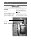
Mounting . . . . . . . . . . . . . . . . . . . . . . . . . . . . . .11
Power Connections . . . . . . . . . . . . . . . . . . . . . .12
Engine Start Control Connections . . . . . . . . .13
Exerciser Option . . . . . . . . . . . . . . . . . . . . . . . .14
Functional Test . . . . . . . . . . . . . . . . . . . . . . . . .15
Jumper Positions . . . . . . . . . . . . . . . . . . . . . . . . .6
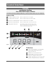
Control Interface . . . . . . . . . . . . . . . . . . . . . . . . . . .17
Indicator LED’s . . . . . . . . . . . . . . . . . . . . . . . . .17
Pushbuttons . . . . . . . . . . . . . . . . . . . . . . . . . . . .17
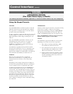
Using the Keypad Controls . . . . . . . . . . . . . . . .18
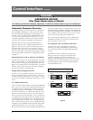
Automatic Generator Exerciser . . . . . . . . . . . .19
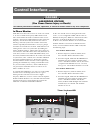
In-Phase Monitor Operation . . . . . . . . . . . . .110
Page
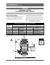
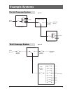
Example Systems . . . . . . . . . . . . . . . . . . . . . . . . . . . .11
Partial Coverage Systems . . . . . . . . . . . . . . . . .11
Total Coverage Systems . . . . . . . . . . . . . . . . . . .11
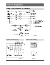
Typical Diagrams . . . . . . . . . . . . . . . . . . . . . . . . . . . .12
Power Circuit Schematic . . . . . . . . . . . . . . . . . .12
Power Panel Layout . . . . . . . . . . . . . . . . . . . . . .12
Interconnect Plug . . . . . . . . . . . . . . . . . . . . . . .12
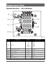
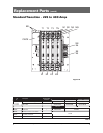
Replacement Parts . . . . . . . . . . . . . . . . . . . . . . . . . .13
Standard Transition 40-200 Amps . . . . . . . . . .13
Standard Transition 225-400 Amps . . . . . . . . .14
Troubleshooting . . . . . . . . . . . . . . . . . . . . . . . . . . . .15
Table of Contents
Authorized Service
For GE parts and service, call: 773 299-6600
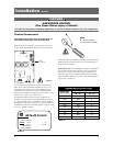
Introduction
GE Zenith Transfer Switches are used to provide a continuous source of power for lighting and other critical loads by auto-
matically transferring from source 1 power to source 2 power in the event that source 1 voltage falls below preset limits.
Voltage sensing and system control is performed via a state-of-the-art microcontroller located on the cabinet door.
It is designed to give highly accurate control of the transfer switch system.
All GE Zenith transfer switches are designed for use on emergency or standby systems, and are rated for total system or
motor loads. Transfer switches are UL Listed under Standard 1008 and CSA Certified under Standard C22.2 No. 178 and
IEC Listed under Standard 947.
NOTES: A protective device such as a molded case circuit breaker or fused
disconnect switch MUS
T be installed on both sources of incoming
power for circuit protection and as a disconnection device.
All references made within this manual about the term “S1” or
“Source 1” relate to a Normal Power Source. All references made
about the term “S2” or “Source 2” relate to an Emergency
or Alternative Power Source.