9
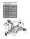
3. ASSEMBLY INSTRUCTIONS – LAZER Z HP
(
See Section 4 for Lazer Z and Lazer Z XP)
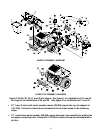
3.1 ASSEMBLY DIAGRAM
Ref. No. Qty Description
1 Ref Engine Guard 44,48 only
2 1 Bagger Mount Weldment
3 8 5/16 – 18 X 1.00 Hex Head Screw
4 1 Hood Assembly
5 2 Bag Assembly
6 1 Upper Tube
7 1 Lower Tube Assembly
8 3 #10 – 24 X .75 Truss Head Screw
9 3 #10 Flat Washer
10 3 #10 – 24 Nyloc Nut
11 1 Blower Assembly
12 Ref Rear Weight 52 only
13 Ref Spacer 52 only
14 8 5/16 – 18 X 1.75 Hex Head Screw
15 4 5/16-18 x 18 Whizlock Nut
16 2 Clevis Pin
17 2 Hair Pin


