18
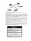
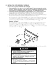
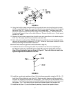
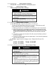
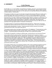
20. 72” units below serial number 260,000 will require the deck to be modified by adding the
accessory mounting tube. Exmark kit 103-0583 contains the parts and templates required.
Follow the instructions in this kit. These decks will also require drilling the hole at the front
upper corner of the discharge opening to ½ inch diameter. (See Figure 6). Touch up with
red paint Exmark P/N 850337.
FIGURE 6
All units
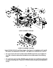
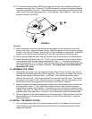
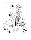
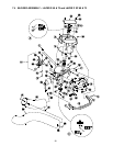
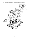
21. Mount the blower on the deck by sliding the mounting pin into the tube at the rear right
corner of the deck. Swing the blower closed. Adjust the position of the front pin to engage
the slot in the front of the deck. Use the latch to lock the blower in this position. Adjust the
tension on the latch to draw the blower up to the deck, yet allow for release by hand.
22. Pull the spring loaded idler back and slip the belt over the top sheave on the deck spindle.
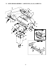
23. Install the plastic belt cover (Item 10). On 60” units the outside end of the cover is slotted
and can slip between the two washers assembled in step 17. The plastic knob does not
need to be removed. On 72” and 52” units the cover has a hole, and the plastic knob must
be installed after the cover has been positioned. The original belt cover stud must be
removed on 52” units.
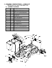
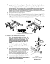
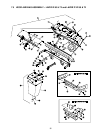
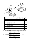
4.4 ASSEMBLE THE TUBES
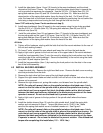
1. Remove the six screws, nuts, and washers (Items 4,5,and 6) from the lower tube (Item 3)
and slide the lower and upper tube (Item 2) together. The arrow on the upper tube should
align with the dimple on the lower tube. On 60 and 72 inch units there are two sets of
holes on the lower tube. The first set reached is for use with Lazer XP units. The second
set reached is for Lazer Z units. Align the arrow on the upper tube with the dimple on the
lower tube and slide them together until the proper set of holes is reached.
2. Fasten the upper and lower tubes together using three of the hardware sets removed from
the lower tube in step 14. The heads of the screws must be inside the tube to prevent
accumulation of grass inside the tube. The washer and the nut should be installed on the
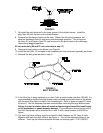
outside of the tube. On Lazer XP units, use the remaining three hardware sets to plug the
exposed holes in the lower tube. On Lazer Z units, discard the remaining hardware sets.
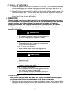
3. Slip the upper end of the tube assembly into the hood opening. Slide the lower end of the
tube assembly over the blower outlet and align the notch with the tube latch. Latch the
tube to the blower.
4.5 INSTALL THE WEIGHT PLATES
1. The four weight plates (Item 35) must be installed under the front panel of the floor pan.
These weights give proper balance to the machine when the removable portions of the
bagger are removed.