


15
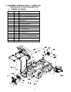
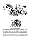
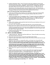
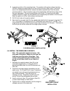
5. Install the side plates (Items 14 and 15) loosely to the mount weldment and the wheel
channels of the Lazer Z frame. The flanges on the side plates should face in towards the
unit to provide the maximum tire clearance. Use the 3/8-16 x 1.00 bolts (Item 23), 3/8
spring disk washers (Item 25) and 3/8-16 whizlock nuts (Item 24). Make sure that the
raised portion of the spring disk washer faces the head of the bolt. On 52 and 60 inch
units, the lower bolt on the wheel channel is best installed by positioning the nut behind the
hole using a deep socket and turning the bolt through the hole into the nut.
Lazer Z XP units only (Lazer Z units continue at step 8)
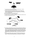
6. Install mount weldment (Item 9) loosely to the rear bumper using the two holes provided.
Use the 3/8-16 x 1.00 bolts (Item 23), 3/8 spring disk washers (Item 25) and 3/8-16
whizlock nuts (Item 24).
7. Install the side plates (Item 16) and spacers (Item 17) loosely to the mount weldment and
the mounting pads on the Lazer Z XP frame. Use the 3/8-16 x 1.00 bolts (Item 23), 3/8
spring disk washers (Item 25) and 3/8-16 whizlock nuts (Item 24). Make sure that the
raised portion of the spring disk washer faces the head of the bolt.
All Units
8. Tighten all the hardware, starting with the bolts that hold the mount weldment to the rear of
the unit and working forward.
9. On Lazer Z units, reinstall the rear wheels and lower the unit from the jack stands.
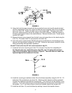
10. Apply a light coat of grease to the front and rear of the upper tube of the mount weldment.
Install the hood assembly (Item 7) onto the mount by slipping the hook portion over the top
mounting tube of the mount weldment. Secure the assembly to the mount using the clevis
pins (Item 19) and hairpins (Item 20).
11. Install the bag assemblies (Item 1) by inserting the hook portion into the slots in the cross
bar of the hood assembly.
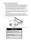
4.3 INSTALL BLOWER ASSEMBLY
1. Lower the deck fully. Remove the right hand belt cover. Remove the belt cover mounting
stud that protrudes from the deck.
2. Remove the deck drive belt from around the right hand spindle sheave.
3. Support the right mower blade and shaft so that it will not fall out of the deck when the right
sheave nut is removed.
4. Remove the right sheave nut, spring disk washer, and sheave from the spindle shaft.
NOTE: On units with wrench flats on the spindle just above the blade use a 1-inch
wrench on the flat sides of the spindle shaft to prevent the spindle from turning. On
units that do not have a wrench flat, block the blade rotation with a block of wood
between the blade and baffles as indicated in the blade service section of the Lazer
operator’s manual. Do not use the blade bolt to prevent rotation.
5. Apply a light coat of grease to the top portion of the spindle shaft where the sheave
mounts.
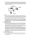
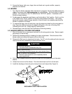
6. Install the double sheave (Item 12) onto the right spindle shaft. Install the spring disk
washer and nut removed in Step 4. Torque the sheave nut to 75-80 ft. lbs. Make
sure that the spring disk washer cone is installed towards nut. See Figure 2.
NOTE: On units with wrench flats on the spindle just above the blade use a 1-inch
wrench on the flat sides of the spindle shaft to prevent the spindle from turning. On
units that do not have a wrench flat, block the blade rotation with a block of wood
between the blade and baffles as indicated in the blade service section of the Lazer
Z operator’s manual. Do not use the blade bolt to prevent rotation. Check blade bolt
torque after completing this installation (115 – 120 ft. lbs.).